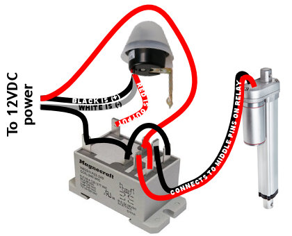
UPDATE: If you have AC power in your coop, a more reliable method uses a Solar Time Table Switch which adjusts automatically throughout the year for daylight hours based on your location.
A question that comes up a lot in my Automatic Chicken Coop Door posts is what’s the wiring diagram with a photocell? Ask & ye shall receive!

One thing I’ll say up front while I still have your attention — the wiring diagram above is NOT WRONG in terms of the photocell wire colors. It’s not what you’d expect. The black wire is positive, white is ground, & red is the switched output (+). Also, the pin wiring for the relay may change slightly depending on which relay you use. For instance, here’s the wiring diagram for the “heavy duty” relay option in the parts list below:

This is a “dusk till dawn” photocell which means the photocell switches on at night. It’s advertised as waterproof & the light sensitivity is adjustable. It also has fairly mediocre reviews on Amazon so if anyone has a better photocell to recommend, please do!
Here’s the parts list:
- 12V waterproof adjustable photocell
- 12V DPDT relay with base or spend a bit more and get a heavy duty relay
- 12V linear actuator, 8″ extension, IP65 rated w/ built-in limit switches & mounting brackets from eBay (or get it on Amazon)
- 12V programmable digital timer ** OPTIONAL — see timer override below.
The DPDT relay is wired as an H-bridge. This means you make an “X” with power to the normally open (NO) & normally closed (NC) terminals so they have reverse polarity from each other. The “common” terminals connect to the linear actuator.
The photocell controls the coil, the coil switches the relay & that reverses the motor. The linear actuator’s built-in limit switches take care of the rest.
IF IT OPENS AT NIGHT & CLOSES IN DAYLIGHT: Flip the leads to the linear actuator where they plug into the relay.
POWER DRAIN: Although daytime power usage is minimal (0.004 amps) when the photocell is only monitoring the light level, the photocell & relay have a constant power drain at night of 0.12 amps when both the photocell & DPDT relay coils are energized. So I recommend only using this photocell system on dedicated power.
You can still use the photocell system with a solar panel/battery setup, but you would need enough capacity to handle the power drain (12 hours night @ 0.12 amps = ~1.5 amp-hours just for operating the photocell). If you need to conserve power, use this timer-driven system instead.
Here’s a video explaining the wiring:
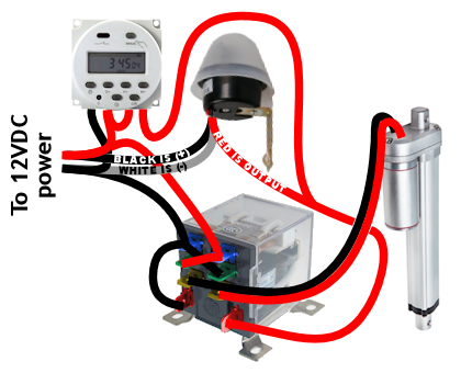
OPTIONAL TIMER OVERRIDE: Don’t trust the photocell? Add a timer so that closing the door happens regardless of whether the photocell works. Here’s a wiring diagram for that:

Set up one timer event:
- start time = forces the door to close
- end time = door available for photocell to open
So for example, start time of 10pm & end time of 5am.
Keep in mind the timer only overrides closing — if you have a bad photocell that doesn’t recognize daylight, the timer won’t force the door to open.
I use a system of timers instead of this photocell system, because where I live has high winds & I’m concerned the photocell wouldn’t be reliable with blowing dust & snow. The timer system also has far less power drain which is useful if you have a solar-powered coop. I change the open & close times every few months to keep pace with daylight. But the photocell method is pretty slick & if it works for you, great.
Any questions, post in the comments below. Hope this helps!


 Back in September 2017, an email address at my small scuba diving company Hero Divers began receiving unsolicited marketing emails from Ruben Harris, ruben.h@trekksoft.io, Product Marketing Manager at TrekkSoft AG.
