
UPDATE: If you have AC power in your coop, a more reliable method uses a Solar Time Table Switch which adjusts automatically throughout the year for daylight hours based on your location.
A question that comes up a lot in my Automatic Chicken Coop Door posts is what’s the wiring diagram with a photocell? Ask & ye shall receive!
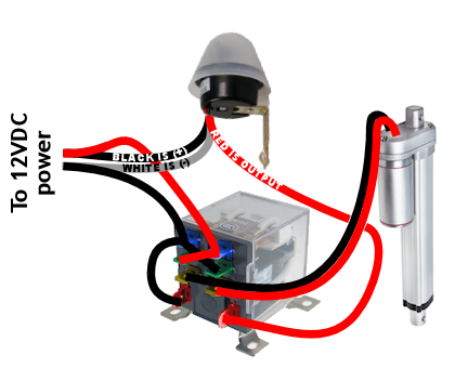
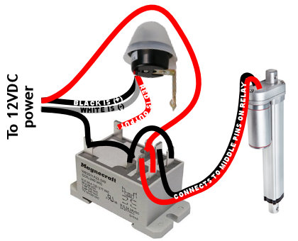
One thing I’ll say up front while I still have your attention — the wiring diagram above is NOT WRONG in terms of the photocell wire colors. It’s not what you’d expect. The black wire is positive, white is ground, & red is the switched output (+). Also, the pin wiring for the relay may change slightly depending on which relay you use. For instance, here’s the wiring diagram for the “heavy duty” relay option in the parts list below:
This is a “dusk till dawn” photocell which means the photocell switches on at night. It’s advertised as waterproof & the light sensitivity is adjustable. It also has fairly mediocre reviews on Amazon so if anyone has a better photocell to recommend, please do!
Here’s the parts list:
- 12V waterproof adjustable photocell
- 12V DPDT relay with base or spend a bit more and get a heavy duty relay
- 12V linear actuator, 8″ extension, IP65 rated w/ built-in limit switches & mounting brackets from eBay (or get it on Amazon)
- 12V programmable digital timer ** OPTIONAL — see timer override below.
The DPDT relay is wired as an H-bridge. This means you make an “X” with power to the normally open (NO) & normally closed (NC) terminals so they have reverse polarity from each other. The “common” terminals connect to the linear actuator.
The photocell controls the coil, the coil switches the relay & that reverses the motor. The linear actuator’s built-in limit switches take care of the rest.
IF IT OPENS AT NIGHT & CLOSES IN DAYLIGHT: Flip the leads to the linear actuator where they plug into the relay.
POWER DRAIN: Although daytime power usage is minimal (0.004 amps) when the photocell is only monitoring the light level, the photocell & relay have a constant power drain at night of 0.12 amps when both the photocell & DPDT relay coils are energized. So I recommend only using this photocell system on dedicated power.
You can still use the photocell system with a solar panel/battery setup, but you would need enough capacity to handle the power drain (12 hours night @ 0.12 amps = ~1.5 amp-hours just for operating the photocell). If you need to conserve power, use this timer-driven system instead.
Here’s a video explaining the wiring:
OPTIONAL TIMER OVERRIDE: Don’t trust the photocell? Add a timer so that closing the door happens regardless of whether the photocell works. Here’s a wiring diagram for that:
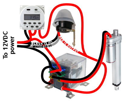
Set up one timer event:
- start time = forces the door to close
- end time = door available for photocell to open
So for example, start time of 10pm & end time of 5am.
Keep in mind the timer only overrides closing — if you have a bad photocell that doesn’t recognize daylight, the timer won’t force the door to open.
I use a system of timers instead of this photocell system, because where I live has high winds & I’m concerned the photocell wouldn’t be reliable with blowing dust & snow. The timer system also has far less power drain which is useful if you have a solar-powered coop. I change the open & close times every few months to keep pace with daylight. But the photocell method is pretty slick & if it works for you, great.
Any questions, post in the comments below. Hope this helps!
Tom
Hi Wick,
Could you please post a diagram that involves a Honeywell Econoswitch that was mentioned in your other post (and you referred to just replacing the photocell) It was a bit confusing, since it still uses the regular timer. I thought it’s doable without additional timers. I have 120V to the coop.
Thanks!
Tom
Hello!
Anybody here?
Wondering if anyone made progress with Honeywell Econoswitch.
Please let me know!
Wick
Whoops sorry, I missed your first comment. I did set up the Honeywell switch a few months ago & it works great. I can do a writeup about it with photos & wiring diagram later this weekend, probably Sunday.
Wick
Hi Tom, here you go: http://blog.netscraps.com/diy/automatic-chicken-coop-door-solar-time-table-switch.html
I mention this briefly at the end of that writeup but I found what looks like a better heavy-duty relay that screws directly into a smaller weatherproof box. So if you’re considering ordering parts for this, maybe hold off for a few more days. I’ll update the writeup about how the new parts work (and an updated wiring diagram for them) by the end of next week.
Wick
I updated that Honeywell switch blog post with instructions for a better relay.
Holland C
Hello,
I am ordering the parts on the list, I want the photo cell to open and close and use the timers as backup. With the recemendation to use 120v with the photo cell will Al the components work with 120v. Thanks
Wick
Hi Holland. NONE of the components that I listed here will work with 120VAC. They are all 12VDC. Where’s the recommendation to “use 120VAC with the photocell”? I don’t think I said that anywhere. However you could use an AC to DC power adapter, potentially with battery backup — see the “power supply” options that are listed halfway through my earlier timer-based chicken coop door post for more help with that.
Steve Smith
First of your post is very informative and has inspired me to build my own photo cell operated door closer for my chicken coop. Looking over your wiring plan I got confused about the “red” wire coming from what I presume to be the power supply along side the “black” hot wire and the “white” common wire. I get the “red” switch wire coming from the timer and the photo cell to the actuator. My question is, is the red wire originally leading to the DPDT switch and the timer a common wire also, or I missing something in my understanding of your schematics.
Again thanks for the diagram, I’d be lost without it and walking out to the coop every morning and evening.
Wick
Ah I can see how that could be confusing. This is 12VDC power, so the black wire from the power supply is ground (-), & the red wire from the power supply is positive (+). You’ll see that standard DC power wire color scheme matches the wiring that runs to the relay & actuator (and timer too, for that option).
The photocell is where the wire colors get confusing — although it is a 12VDC photocell, it oddly follows the typical 120/240VAC wire color convention as you described. That is why I have the text notes on those photocell wires. Other than the photocell, the rest of the wiring follows the standard 12VDC wire color convention of red (+) / black (-).
Mathias
Hi wick I’m not sure if you’ve covered this before but I would like to add in a manual switch to a photocell setup. Would I just wire it to bypass the automation …grab power before it and jump back in after it? Would wiring it in as the optional timer in the photocell work? If so, would I use a polarity switching three pole switch 12v dc? Also would like to thank you for posting these diagrams have been very helpful.
Wick
Hi Mathias, yes you could replace the timer with a manual switch but I don’t think the polarity reversing switch would help, since you already have polarity switching with the relay.
An easy way for a manual override would be to use an SPDT switch. Wire (+) power to the common terminal on the switch, run the (+) lead from the photocell to one side of the switch, & the (+) timer override wire to the other side. That way the settings on the override switch are AUTO / OPEN / CLOSED. I’ll make another wiring diagram for that.
Mathias
Thank u much could you do one that doesn’t involve a time as I’m not planning one. And I want to thank u every much for your time and help this is awesome !!
Ben
Hey Wick! I greatly appreciate you posting these coop door setups. I was able to get the photocell with timer backup to work with the basic DPDT relay, but it stopped opening the door in the morning after a week or two. I can reset the whole thing in the morning by disconnecting the power and reconnecting, and the door opens…then closes when it is supposed to. I assumed this behavior was a bad relay, so I opted for the heavy duty DPDT relay. Unfortunately, the heavy duty relay connections don’t seem to be exactly the same as the smaller cheaper relay, although they look very much the same (just bigger). Do you happen to have a wiring diagram for the heavy duty relay? I’m guessing I have it wired wrong, but I’m having trouble understanding how it should be connected, since I’m not so good at wiring.
Wick
Ah good point, the wiring for the heavy duty relay is different. The coil is still the same: the pair of terminals on one end that are turned 90 degrees from the other 6 terminals. However the wiring “X” goes between the top pair & bottom pair of the 6 terminals. The “common” terminals that run to the linear actuator are the middle pair of the 6 pins. I can do a wiring diagram if that doesn’t make sense.
Ben
I think I got that, but if a diagram is possible, I would be hugely appreciative. 🙂
Wick
Hi Ben, I added a 2nd wiring diagram to the post above for the heavy duty relay. Hope that helps!
Dion Bullpitt
Hi is there a chance of getting a copy of the diagram please having troubles
Charlie Gordon
Completely new to electronics but ordered all the stuff and got the actuator working directly from the DC power supply so I’m pretty chuffed.
Just a quick question regarding the power supply, do I only need one power supply to run both the light sensor, the actuator and the relay? If so, how does that work exactly? Thanks.
Wick
Hi Charlie, yep with this system all the components are 12VDC so you only need one power supply for everything. For the power supply, you can use a DC power adapter, solar panel & 12V battery, etc. Whatever you use just needs to be able to power the actuator which usually draws about 5 amps max, so for instance if you use a 12V power adapter it has to be rated to produce at least 5 amps. All power adapters have the rating info printed on them, for instance “OUTPUT: 12VDC — 1.5A” which means 1.5 amps so not enough power in that example.
For power supply ideas, see this post & scroll down to the “Power Supply Options” section.
Charlie Gordon
Thanks for the help, appreciate it! I’ve got this relay, should this work ok? It’s not the same as the one you’ve got so I’m finding where to hook each thing up a little confusing. Thanks again.
https://www.amazon.co.uk/gp/product/B00LWX9PPA
Wick
Hi Charlie, that relay is the right type (DPDT) but looks like it’s not rated for enough amps. On the side of that relay I see “1A @ 24V”. I think for DC power the amp rating stays the same for lower voltage so it would also be 1 amp at 12V, & that’s probably not enough — most linear actuators are rated for ~5 amps, so you really should get a heavier-duty relay rated for at least 5 amps.
That said, here’s the wiring: the “common” terminals (COM1/COM2) connect to the linear actuator motor. Then make an “X” between the NC & NO terminals — so in other words you connect NO1 to NC2, & NO2 to NC1. Then run power to those two “X” legs (one leg becomes +, one leg becomes -). If it runs backwards from how you want it to, swap the COM1/COM2 leads. With that relay, you also run (+) to VCC, (-) to both GND terminals, & INPUT connects to the photocell.
Hope that helps, any other questions ask away.
Steve
Hi, absolutely love the DIY option. We forked out for a system that had been made by a supposed chicken expert company, yet it consistently fails and i have had to return the system. Now looking to make my own. I’m not an expert at 12volt circuits and wondered if you might have any suggestions for my idea?
I want a light operated door opener so that it keeps pace with the seasons and allows our girls out once it get light and closes once dark. However i would like to add a delay into the system of a few hours. We have two doors one on the coop whic i want to operate just by sunlight the other is on the chicken run. The door on the run i want to open about 4 hours after sun light but then close after dark. This is to reduce the access the girls have to our garden to reduce the effect of them scratching the grass. Over winter the grass doesn’t have time to recover, so by reducing the time they have access will reduce the damage. They will still have access to a large run throughout the day.
How do I introduce a delay time into a light operated system?
Any help would be ver useful. Thank you for your time
Steve
Wick
Hi Steve. The photocell relay turns on at night & off in the morning, so you want to delay that “power off” event by 4 hours… that’s called an “off-delay” & I think most multi-function timer modules support that off-delay mode, like this one. I haven’t tried that specific module so can’t guarantee that works but from reading the documentation, it should in theory.
The other option that might be simpler is this Solar Time Table Switch method. The switch automatically adjusts the event times you give it based on daylight hours at your location. So for example if you set it to close the door 1 hour after sunset & open 4 hours after sunrise, the switch will continually adjust those event times to keep pace with the seasons based on each day’s sunset & sunrise times.
Jesse
Hi Wick,
I want to use the photocell and connect to the 12V battery but was worry about the battery getting drain at night. So if I use the10W 12V solar paneland the 20-amp 12V solar charge controller to regulates power to the battery & automatically disconnects the solar panel at night. Will this set up work to stop the battery drain at night?
This is awesome by the way.
Wick
Hey Jesse, short answer: no. As you said, the solar charge controller just disconnects the panel at night. The photocell relay is “on” at night so it will be a drain on the battery regardless of the solar controller. There’s no way I know around that, because as soon as the photocell relay turns off, the door opens.
The photocell uses about 1.5Ah for a 12-hour night. A 10-watt solar panel usually can make 0.6 amps, so as long as you get 3 hours of full sunlight each day, 3 hours * 0.6 amps = 1.8Ah… so in theory the 10-watt panel should keep up with the photocell drain, but there’s also running the charge controller, recharging the battery, running the door open & shut each day … & you might get a few cloudy days. So the 10W panel is probably too small. I’d try a 20W panel.
Also it’s not good to repeatedly discharge the battery past 80% so I’d go with a battery with at least 15Ah capacity, like a lawn mower battery. Hope that helps!
Bruce
Hello, thanks for keeping up with this information. It looks like it’s been a major help to so many of us chicken keepers.
I had a question about the photocell drain at night. Couldn’t you put a timer on it so that it turns off at say 10:00 pm and then turns back on at 2:00 am?
Appreciate your thoughts. Hope I’m not over simplifying. I’m sure I’m missing something.
Wick
Hi Bruce, sure that’s a great idea. You’d just need to have the timer cut power to the whole system (not just to the photocell) because otherwise the door will open.
Tom
How would I wire a switch in so that if I wanted to clean the coop I could close the door with the switch?
Wick
Hi Tom, sure — wire a SPST switch between the positive (BLACK!) wire of the photocell & the red (OUTPUT) wire of the photocell. When you turn the switch ON, it will bypass the photocell & the door will shut. The only caveat is turning the switch OFF just hands door control back to the photocell — it won’t force the door to open, but it will open if it’s daylight.
Don
Hi wick,
I’m using a 12v reversible motor. Does this relay stop the motor when the door is fully opened and closed? How do I run it for 10 seconds? Thanks
Wick
Hi Don, the relay doesn’t stop on its own. My setup works because linear actuators have internal limit switches. You could either add external limit switches to your setup, or as you mentioned you could have the motor run for a short timed period (would probably mean adding another timer module). I recommend the limit switches. They’re easy to wire up.
Don
Hi wick,
I decided to use it without photocell.
So I’ve got 12v reversible motor, white colour timber, DPDT relay and 2 limit switches. Could you please guide me how to wire these together to reverse the motor with this timer. Many thanks. Don
Don
Hi Wick,
I’m absolutely stuck with my door opener. I’m using the photocell system and I’m using reversible 12v motor. As you advised I fitted two limit switches but it doesn’t work properly. Could you please guide me how to wire the switches to photocell and DPDT relay. Many thanks.
Wick
Hi Don, sure. This may be confusing, if so let me know & I’ll try to come up with a wiring diagram.
In my wiring diagram, see where I have positive power to the two terminals on the relay? Not the photocell output — I mean the positive (red) wire straight from the power supply. I have it run to one relay terminal & then jump across the short distance to the other terminal. So rather than connecting positive power to those 2 relay terminals in series like I have it in the wiring diagram, instead you’ll want to have that main positive power wire split into two separate wires, put a limit switch on each, & then run each positive (now limit-switched) wire to one of those two relay terminals. So basically they each get their own limit-switched positive power wire. Then test which limit switch controls stopping which direction of travel. That should do the trick.
Don
Hi Wick, thank you for your reply. I really appreciate if you could send me a wiring diagram as it’s a little confusing for me. Many thanks.
Don
Don
Hi Wick,
My email is madura_j@hotmail.com
I really appreciate if you could send me a diagram with two limit switches. Many thanks
Don
Don
Hi Wick,
I managed to do it and it’s working perfectly. Many thanks.
Wick
Hi Don, great to hear. Nice work.
Dion
Hi, I have a general purpose Eco Worthy controller with manual over ride switch for a linear actuator, my question is can I run a photo electric switch primarily and if so could you explain how I would go about wiring it up please. Thank you.
Marc
Hello Wick,
A message from the Netherlands here!
I have got the exact ‘ingredients’ as in your diagram with one exception.
The black line coming from the left leads to pin 4 (the middle horizontal pin on the right) and pin 7 (the vertical pin on the bottom left) Before it does so however it runs over pin 1 (the top left horizontal pin) and I am not sure whether it’s connected to that pin or not. That’s question 1.
The 12V photocell I’ve got is the same BUT there is a black, red and GREEN wire. So green instead of white. According to the manufacturer red is load, black is the source (so far so good) and green is common +. Now, ‘your’ photocell has a white wire and that’s – but – is not the same as common + so it’s not just the colour that is different.
In other words, I am going nuts and can’t get it to work!
On the table are 2 photocells (1 as a spare) and 2 relays (also 1 as a spare) and I even got 2 actuators. They work alright but nothing works when hooked up!
So, question 2, what do I do with the green wire?
Thank you!
Wick
Hi Marc, Question 1 – yes, ground is connected to the top/left horizontal pin too. In other words, +/- are connected in an “X” across the top 4 terminals, & (-) loops down to one of the coil terminals too. Question 2: Hmm that’s a tough one, I’d have to see the instructions or send the exact model & I’ll take a look. What you wrote sounds right. You sure it’s a 12V photocell?
Marc Dekker
It’s the same as in your picture and the sticker says ’12V’. I actually got two, one as a spare! I found help on an electronic forum but none of them worked and in the end the conclusion of the experts on the forum was. ‘Both are utter rubbish!’
I then decided not to waste any more money on AliExpress and bought a real cell from https://www.tme.eu/
I got 3 coops now, 1 is divided in 2 sections. In total there are 4 doors, 4 actuators, 1 cell, 1 transformer 220V – 12V and 1 relay.
All work beautifully!
Wick
That’s great, Marc. Good to hear it all worked out & that you got it working with a good-quality photocell. Thanks for the note!
Tom
Is there an option that the timmer also overrides the opening?
Wick
Sure, you could put an additional timer on the red output wire from the photocell, just before the relay. Then you’d set the timer to trigger (on) for all the hours you want to allow photocell door control. So basically any time this additional timer is off, the door is open.
Paul
Mike your explanation and diagrams were the very best for helping me set up my automatic door. I went with photocell, actuator, relay and a 12 volt auto battery with a battery maintainer just to be safe.
Since I can’t see the pop door from my house I plan to mount a 12 volt LED light on the side of the coop that will come on when the relay is in night mode. Currently plan on an amber light like the ones truckers decorate their big rigs with. It will be wired with ground directly to the battery and hot to the relay. I’ve already determined which side of the relay is hot at night. Your thoughts will be appreciated.
Tom
Hi,
Do you have any idea how powerfull must be the 12 V power source? I am planning to use my computer charger but i don’t know how many amps are required for optimal working.
Wick
Hi Tom, sure — the 12V power source just has to match the maximum power requirements of the linear actuator or whatever motor you are using. Most 12V linear actuators draw about 5 amps max (pushing hard under load), but as long as your door closes easily, you probably could get away with a 2-3amp power supply & the linear actuator just won’t have as much power as it would normally if it encounters resistance. The danger for using an undersized power source can cause it to heat up & burn out.
Jason L Maslow
Hello Wick,
I’m not sure if you still check this, but thank you for the great diagrams and information. I think I followed your wiring diagram correctly for the photocell with the timer and it opens and closes in manual mode and will close if I cover the photocell, but in the auto mode it will never turn on (always shows off). I have made sure the days of the week are correct. Do you think this is a bad timer or something I messed up with wiring? Thanks for your help. Jason
Wick
If the timer works in manual mode but the timer never triggers in auto, then I’d double check the timer settings. The timer’s manual mode just triggers the timer relay in the same way it triggers automatically — you’ll hear the relay solenoid click & the same red light goes on. I don’t think there’s anything wrong with your wiring.
With the timer settings, maybe hit the reset button & reprogram it from scratch?
Jason
Thank you. After I reset the timer and pressed the manual button it cycled through an off and auto option and I had it on off previously. It works perfect, now. Much appreciated!
Kevin
Seems that I ordered a different relay, do you know if it will work?
92S11D22D-12
Coil: 12VDC
When I hook it up and plug in the outlet it buzzes …any ideas would be greatly appreciated.
Wick
What are you using for a power source? It sounds like maybe it’s not providing enough 12VDC amps but that’s just a guess. The relay definitely shouldn’t buzz, it should click & then be silent.
Kevin
I realized I needed a power source, I was just plugging into the wall outlet. I now have a ac adapter like you recommend on your power source page….did not read that at first.
Now the buzzing is gone, but I have 12 vdc to both middle pins on the relay.
Am I reading the diagram right that both x’s should have power to them not from the photo cell? Or maybe I am confused on reading the diagram.
Kevin
Update, I had wired it wrong so now I my power to 1 of the center pins. But can’t get photocell to flip.
Wick
You may have burned out some of the wiring in the photocell, actuator etc, since it sounds like you connected it directly to the 120-volt AC wall outlet at one point. That’s my guess why the photocell isn’t working now.
Wick
Yes, the photocell only supplies power to the relay coil. And yes, the “X” has 12VDC straight from your power source. You should figure out which terminals are the “normally closed” (NC) set & which terminals are the “normally open” (NO) set. Those two sets get power in opposite polarity from each other, which is why the wiring looks like an “X” to those 4 pins. Then the “common” (COM) set of terminals run to your actuator.
Kevin
Does the photocell have to be special…I got mine from my local hardware store and can be used on outdoor lights. Seems now like it’s not switching when I cover it with towel.
Andre
Hi Wick,
You are a total hero for helping all of us clueless farmers out haha, electricity is not something I specialize in.
I have a photoelectric switch, a 4inch actuator, a relay, and a 12v transformer AC transformer. I also had some wiring plans I found online, but (just my luck), it is not working as it should, possibly because the plans are for DC.
Do you have an email I can contact you at to pick your brain about this set-up, I know you have a few similar setups but not this specific one, maybe you’d be interested in helping me figure this out and I can send you some pics once its working to add to your website. Please let me know. I and my chicken thank you.
michael mazur
great write up, got er done to make a variation, a day time deer feeder, lid opens during the day, and shuts the buffet at night. pair of 10AH batteries, a 30 watt solar battery charger, the 8 pin dpdt relay, and an adjustable light sensitivity photo cell. the actuator is strong, much stronger than I thought it was going to be but hey, it isn’t struggling!