
UDPATE AUGUST 2016: I’ve redesigned this automatic coop door so that one timer controls opening & one timer controls closing. See this blog post. Note that the parts list changes a bit with this new automatic coop door design.
 When we first got our chickens, each night I’d walk up to the coop & close them in. That worked great until the night I’d fall asleep putting our 3 kids to bed, or start watching a late-night movie, & suddenly OOOOHH SHIT, THE CHICKENS!!! …followed by a guilty run to the coop, wondering if I was about to find sleepy hens or a poultry massacre.
Chickens are a tasty snack for lots of predators. It’s a tough spot in the food chain. Locally we have raccoons, possums, weasels, foxes, coyotes, neighborhood dogs, hawks, eagles, owls… my friend Chris who loves fried chicken a little too much… Raccoons at night were my main concern.
A few months of this started to feel like Russian roulette. Like so many other pet chicken owners, I decided to try building an automatic chicken coop door.
On Youtube there are plenty of automatic chicken coop doors that use string to raise/lower a guillotine-style door, sliding vertically in a track. It’s a safe design — it won’t kill chickens if one gets in the way while closing — but I was worried the door would get jammed from ice & snow.
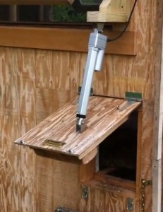
I wanted something with a direct drive to use with a door that swung up on hinges to open. Here’s what I ended up using:
- 12V linear actuator, 8″ extension, IP65 rated w/ built-in limit switches & mounting brackets: ~$55
- (2) 12V programmable digital timers: $5 each
12V DPDT relay w/ base: $3**SEE UPDATED RELAY METHOD HERE- Wiring, inline fuse holder/fuse, terminals: $6
A/C dedicated power option:
- 12V 6-amp power adapter: $7
A/C with power outage protection:
D/C solar power option:
Total cost: $81 dedicated A/C, $111 A/C battery backup, or $123 solar D/C ($138 w/ charge controller)
Linear actuators use a small motor to move an extendable/retractable arm. The arm moves very slowly with 50 to 200 pounds of force. Get one with built-in limit switches & an IP65 rating so dust/water/ice/snow is no problem — pretty great for chicken coops. There are various lengths for the arm travel distance. I got the 8″ model & it takes about 20 seconds to extend/retract the arm … plenty of time for chickens to move out of the way. Small 12V actuators like these usually have a rating of around ~5 amps, so make sure to use a relay, fuse & wiring that’s appropriate. Also make sure the actuator comes with mounting brackets, or you’ll need to come up with something.
Typically, actuators with higher force ratings mean slower movement. Same goes for the arm extension length — longer extension means your door closes more slowly — more time for chickens to get out of the way.
Next, how to power it. If your coop is near A/C power, you could use a 12V power supply instead of the battery/solar panel. Just make sure the power supply is rated for enough amps to reliably drive the linear actuator motor. Better yet, use a 12V battery permanently hooked up to a battery maintainer & you won’t ever have to worry about power outages.
Our coop is on wheels & we move it around our field far away from A/C power, so I needed it to be self-powered. Linear actuators only draw a few amps so a small 12V battery will do the trick — I had an old one lying around that wouldn’t start the lawn mower anymore, but worked great for the coop door.
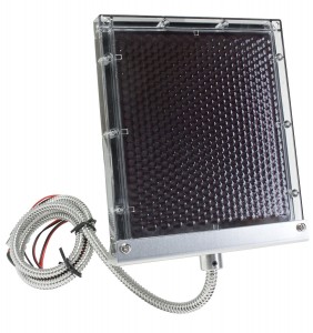 To recharge the battery, I used a small 1.25-watt 12V solar panel. Since the panel’s power output is so low, it acts as a trickle charger, & that way you may not need a solar charge controller as long as the panel is in direct sunlight for most of the day. I’d still recommend a charge controller to make sure the panel doesn’t have a net drain effect on the battery in winter or other low-light conditions.
Last challenge was for the door to open in the morning & close in the evening. I went with a simple setup with very low power draw: two programmable 12V timers.
THE TIMER SETUP BELOW IS OUTDATED. PLEASE SEE THE UPDATED METHOD HERE.
The first timer (the “power timer”) switches on twice a day for 1 minute each to provide power to the actuator. The second timer (the “reversing timer”) energizes a DPDT relay concurrently during one of the power timer events to reverse polarity to the actuator. That opens & closes the coop door.
The last piece is a 12V DPDT relay wired as an H-bridge. This relay has 4 sets of +/- pins: normally closed (NC), normally open (NO), common, & coil. The coil switches the common between the NC pins to the NO pins. For the H-bridge setup:
- connect your power source (+/-) to the timers’ power inputs. Fuse on the (+) wire.
- both timers: jump power (+) over to the 1st switch pin.
- power timer: connect 2nd switch pin (+) to a NC pin on the relay.
- jump that same NC pin (+) to a NO pin, but with opposite polarity.
- reversing timer: connect 2nd switch pin (+) to a coil pin (doesn’t matter which one).
- connect the linear actuator (+/-) to the common pins.
- connect ground (-) to the remaining open pins on NC, NO, & coil.
If when you’re all done the actuator operates the opposite from what you want, just flip the actuator’s connections to the relay’s common pins.
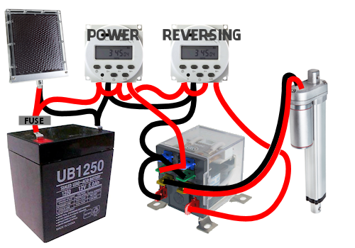
THIS WIRING DIAGRAM IS OUTDATED. PLEASE SEE THE UPDATED METHOD HERE.
Next, program the timers so their clocks are set identically. Let them sit for a few days & figure out which timer is faster than the other. Use the faster timer for the reversing timer.
Power timer: set for two daily events (morning & night) of 1 minute each. For example, 6:30AM- 6:31AM and 9:00PM – 9:01PM.
Reversing timer: set to run concurrently with the morning power timer event, so it comes on sooner & stays on longer than the power timer. For example, 6:30AM – 6:35AM. I prefer the morning run so if anything goes wrong it only means the door won’t open (no big deal).
Whenever you change the time, make sure the reversing timer is always just a bit ahead. This way you can have the morning event start at the same time on both timers.
THE TIMER SETUP IS OUTDATED. PLEASE SEE THE UPDATED METHOD HERE.
Check the timers after a month. I was surprised to find my timers get about 20 seconds off from each other. To compensate, I set my reversing timer event to stay on for 5 minutes — energizing the relay coil is a very minor drain on the battery. That way my system can run for over a year before I’d have to resync the timer clocks. I change the timer settings 3-4 times a year anyway, to adjust for daylight.
Here’s the whole system in action:
UPDATE: In the video I mention mypushcart.com as a good source for the actuator, but they don’t include mounting brackets. Lately you can find IP65-rated actuators on eBay with mounting brackets included for the same $60 price, with free shipping.
sanil
Dear mike
I am from Australia ,i liked your chicken coop design,and i ma planing to make automatic a vertical sliding door with 12V dc motor(car power window motor) my problem is reversing the motor in evening.i beleve your relay diagram van change over the polarity.I already purchased 2 of 12V timer switches and few limit switches to control opening,(my question is which relay has to use for 12V 0.8 amp power supply.if you can give me a relay no or spec it will be very helpfull .hoping your reply.i had found many 12V relay in ebay ,i m bit confused which suit for me
Wick
Hi Sanil, yes the relay/ dual timer setup I used reverses polarity when both timers are on at the same time. The DPDT relays I used are rated for 20 amps at 12VDC (10 amp at 24VDC), which is far higher than necessary. Most regular-size (not micro) relays are in this amp range. However your 0.8 amp power supply may not be enough for the car window motor.
Nick
Do you find that the door is open far enough for the chickens? It is hard to get a good idea of the clearance you have from the ramp to the top of the door and if the chickens have any issues getting in and out. Anything you would have done different or are you pretty happy with the results? I’m looking at setting up an automatic door here pretty quick. I’m sort of leaning towards using a daylight sensor of some sort but I might just stick with the timers at first. This is all new to me so it is easier following someone’s design at first.
Wick
Hi Nick, yes the door opens with plenty of clearance. When it’s open it’s more than a foot to the ramp. They are so excited to go outside they usually duck through when the door is just half-open. Fully open, there’s plenty of room. You can adjust the attachment point on the door closer to the hinge, so even if your actuator arm only has a few inches of travel, it will still swing open the door by much more. Any other questions I can help with, let me know. Good luck!
bob
quetion:
can you email me the actual motor you bought for the solar power automatic door opener. I see all your parts but if you can send me link on that motor (name of motor, speed, e.t.c. Much appreciated
bob
Wick
Hi Bob, see the equipment list in the article. The prices in the list are links to where you can buy each item.
That linear actuator I used is a generic brand, 8″ stroke at 0.4 inches per second, so it’s a ~20 second run. The lowest-power actuators I ran across had 100lbs of force, which is plenty. Any 12VDC 8″ linear actuator that’s rated IP65 (outdoor use) or higher with built-in limit switches should work just fine for a coop door.
The main problem I found was the cost of linear actuators are all over the place. For instance Auto Express sells their generic-brand actuator for $109, almost double the typical cost. So make sure you don’t overpay. Also make sure the linear actuator you buy comes with mounting brackets.
Mike
Hi Wick
I have to say that your posting, with parts list and schematic, and the video are the best quality I have seen in making a auto chicken door.
I would have never known that I would need 2 timers. I would have thought that once cycled, the timer would shut offandwhen it went on later, the timer would reverse the action of the actuator. So the 2nd timer is needed to reverse polarity? Correct? In any event, your setup and site here is exceptional, and I have looked all over. thank you so much. Mike. Ps. please email me if you can on the purpose again of the 2nd timer. Iam learning. thks. mike
Wick
Hi Mike, I couldn’t find a (single) timer that could also reverse polarity. So that’s why it takes 2 timers, at least the way I did it. One timer provides power for the open & close events, & the other reverses polarity for 1 of the events.
Just make sure you use the faster timer for reversing & set up the timer events as I wrote in the post, otherwise the system might not work reliably for long.
Every few months I reset the timer cl0cks & change the event times to keep up with daylight. So far the whole system has been working great & it’s been several years. Good luck! Any more questions, fire away.
Art
Great info however I very much would appreciate a closer view of the connections on the timers and the H-bridge (12V DPDT relay?) or an enlargement of the terminal connections. I’ve read this several times but I am one of those that needs VERY clear instructions so I don’t screw up something. Also, clicking on your link to 12V DPDT relay brings up something that does not look like yours pictured above. It has a socket base. Is that where your wire connections are made?
Wick
Regarding the connections on the timers, they match my diagram exactly. On each timer, there are 4 spade pins in a row. That matches the 4 wires per timer on my wiring diagram.
Regarding the 12V DPDT relay: the relay I suggested can unplug from the socket base, so you’re free to use it either way. The socket base simply adds screw terminals, & has screw holes so you can mount the relay to something. Here’s a photo of a socket base. You can see there are 8 pins from the DPDT relay, which correspond directly to the 8 screw terminals on the socket base. I didn’t use a socket base for my project only because the relay I bought didn’t come with one. Instead I used a metal strap to mount the relay sideways, & soldered quick disconnect spade connections on all the wires for the relay pin connections. The socket base would have been very convenient.
Hope that helps! Any other questions, fire away.
Ricky
Hi there…nice project..what if you set the reversing timer 1 minute sooner and 1 minute later than the power timer? Like you set the on time of the power timer to 6:30 am for 1 minute and set the reversing timer to 6:29am..maybe i don’t get it..i’m not a geek when it comes to circuitry..
Wick
Hi Ricky, yes that’s exactly the idea — if you didn’t see it already, I explain this in detail near the end of the article.
As long as you go through the step of figuring out which timer is faster & make that the reversing timer, AND set the reversing timer’s clock to a few seconds ahead when you sync them, the reversing timer will always be ahead of the power timer. That means you can just set the same start time on both timers which simplifies things. The 5+ minutes you add to the reversing timer event end time is the only adjustment you need to handle the slower power timer clock.
Otherwise if you don’t bother with figuring out which timer is faster, then you’d do it your way with adjusting the reversing timer’s start AND end times — but in that case I’d set the reversing timer event to start 5+ minutes (rather than 1 minute) ahead of the power timer & stay on 5+ minutes afterward. That way the setup will handle months of compound clock inaccuracy in either direction (slower or faster) since you don’t know which way that will happen. The only downside there is that setup draws solenoid power for 10 minutes each day, versus 5 minutes.
Tom
wick,
Great,plan I am trying to get mine going I can get it to open but it will not close it seems that second timer is not working my setup matches yours any ideas or eperience you can share of where I maybe missing a step?
Wick
Hi Tom, those timers are cheaply made so it’s definitely possible you have a defective timer. You could try switching the timers temporarily.
The only time I’ve had a timer not work is when the 12V power source wasn’t strong enough, like a dead or dying battery. In that case the LED light still goes on, but the timer’s internal relay doesn’t have enough power to close the circuit.
Otherwise if the timer is working, the problem might be the wiring to the DPDT relay. If you send a photo I might be able to troubleshoot it. Good luck!
Tom
Wick, Thanks for the info we figured it out we were setting the timers wong. Now it works great we’re so happy.
Rich Brostrom
Thank you for your post! The drawing illustrating the wiring was very helpful but in my case the black and red wires (on the left side of the timer as you are looking at it) needed to be reversed on both timers for them to work. I believe I have the same model timer. The other thing I didn’t initially pick up on was that the reversing timer is only used for one of the operations, in my case the left timer opens and and then the second program closes and needs the reversing time to close the relay.
I’m posting this in case someone else is having difficulties.
Thank you again for sharing.
Mark Henderson
Any reason you didn’t hook this up to a Photo Control Sensor and a SMAKN® DC 12V 2CH 2 Channel Isolated Optocoupler High/Low Level Trigger Relay Module. The reversing of polarity is built into this design. This way you won’t need to reprogram the seasonal daylight changes. I am using this system with reliablity. It’s also cheap to set it up this way.
Wick
In terms of reversing polarity, I imagine you wired those two SPDT optocouplers into an H-bridge (right?), which accomplishes the exact same function as my single DPDT setup. Are there any benefits to using the two optocouplers?
In terms of why no photo control sensor, I decided I’d try the timer method first – I wasn’t sure if the photo sensor was going to be reliable enough with snow/dust etc. Adjusting the timer a few times a year hasn’t been a hassle, but I bet the photosensor is pretty nice.
Mark Henderson
Thanks for the reply. The relay is built into a one piece unit. If you look this up on Amazon I posted a wiring diagram with my review. I’d love to take the credit for it but I got help from a electrican that I know.
When the weather warms just a bit I plan on adding a timer to be able to select from operating the door by timer or photocell. I have already wired the main power to a ON/OFF/ON toggle switch.
Thanks for the clear details and wiring plans.
bobby
Hi Mark. Would you be willing to share your photo of your wiring in a email. I did see it on Amazon but it’s to small to see. Thanks. [email redacted]
Wick
Hi bobby, Mark’s photo on Amazon is actually a lot larger & more detailed than they show it. Here’s the full-size image: https://images-na.ssl-images-amazon.com/images/I/71uGj3903eL.jpg
Mark Henderson
I sent this to your email address. My system is wired to a lawnmower battery with a 12v Black and Decker maintainer. We lose power and this always guarantees the door to close. I really need to post some pics. It’s a sweet setup.
Alan
Hi Wick, hey with this awesome system, can you set the door to open at first light & close at dark?
As i need it to be open all through out daylight hours so they have access to the nests & feed.
Wick
Yep that’s how I have it set up. Door opens at 6am & right now I have the door close at 7pm. I adjust it twice a year (spring & fall) for the change in daylight, so the door stays open until 9pm in the summer. Any other questions, fire away.
Mark Henderson
My setup open and closes by a photocell. No need to seasonally change the times.
Paul Hinson
I designed mine with a photocell, relay (DPDT) and an on-off-on switch (DPDT) for the controls. I also used a linear actuator and because I have AC in the coop, a 12 VDC power supply used to power LED’s. The DC comes to the center of the switch and is wired to be polarity reversing exactly like the relay. The photocell is wired directly to the power source and the output wire goes to the relay coil which is referenced to negative.
The switch can be turned to the off position to prevent movement, plus it can used to move the door to the desired position. The main difference is I used a cutting board as the door which is very slippery inside the wood channel to minimize drag. I mounted everything in a plastic box to protect it from the elements.
Wick
That’s neat! I didn’t use the photocell because I wasn’t sure how much power it would use & if the solar panel could keep up. If you have external power in the coop, I bet the photocell is the way to go.
Mark Henderson
I also used a cutting board for my door. For my guides I took a PVC brick molding J channel and reduced the slot down on my table saw then reglued it back together with PVC cement.
I had to mount the actuator on the side because of an upper window we didn’t want to loose. I counter balanced the other side so the door wouldn’t rack. Then added a micro switch that turns on a red LED when the door is closed and a green LED when the door is open. Those are mounted so they are visible from the house.
This is fun stuff! My wife thinks I’m nuts but loves the things I come up with.
Bill
Any updates on a photocell???
Wick
Hi Bill, I bought a photocell but haven’t wired it up yet. Just waiting for better weather. I’ll post a detailed update when I get to it. Also I found an easier way to wire the timers using two SPDT relays, where one timer controls opening the door & the other timer controls closing, which is a little more straightforward than the way I did it originally – I’ll post about that too. Thanks for checking in.
Bill
Good news…i just wired mine up…I think I’ll wait untill you post wiring diagram
Rich
Can you post on this thread Wick as I am setting up my actuator and wiring next week. Would love to see how you have it set up
Wick
Hi Rich, got sidetracked for a few months there — I’ll have that new design posted by the end of next week.
Mark Henderson
Follow the thread up further to see how it’s done. It’s cheap and easy.
Bill
I just finished mounting photocell and wireing… Pretty simple to do…i just watched the coop door close at sunset. I’m pretty happy with it..thanks to all involved…Bill
Bill
After 3 days my battery is dead…Its been cloudy and I think the photocell is drawing a lot of amps….I’m not sure in what direction to go
Bill
I just now had time to check the battery….its 11.5 volts…It appears that the volt meter I used failed……so its most likely due to the cloudy days….I’ll moniter it and see…
Wick
Hi Bill, the photocell is definitely a small constant draw, & it looks from Mark’s schematic that both relay coils stay energized while the photocell switches on, so that’s an added power draw for all daylight hours.
The photocell method is slick but I think that design really needs a constant power source. I think Mark Henderson used a battery along with a trickle charger permanently connected to the battery. Most trickle chargers/battery maintainers are at least 1 amp & that should keep up with the constant power draw of the photocell & relay coils. The battery provides enough amps for when the motor is running & also handles power outages. That battery/charger setup should work great as long as you have AC power at your coup like Mark has. Paul Hinson used a dedicated DC power supply with enough amps (probably 5-6) that he didn’t need a battery, & that works great too except in power outages.
With my timer system, I didn’t have AC power available at the coop so I designed it so use the smallest power draw that I know how. The digital timers don’t draw any significant amps for 99.9% of the day, except for a few short minutes when the timer relays & DPDT relay kick on while the door is opening/closing. That’s why that system works so well with just a small solar panel & battery.
What are you using for a power source besides the battery?
Bill
At this time it’s battery only…with the one watt solar panel…the best I can determine the photocell has a one watt drain, not counting the relays. I’m undecided on buying a larger solar panel or just bite the bullet and run 120 volt service to the coop.
Wick
I think the problem with the photocell setup is the photocell has a relay coil for its internal switch that’s energized during either the entire day or entire night hours depending on how your photocell works (day-on or night-on) … plus the draw from the relay(s) for the linear actuator which are also switched on for many hours with that setup… You could use an interval-on timer relay to cut power to the actuator relay(s) after a few minutes, but there’s no way I know of around the photocell problem. Like you said, I think you’d have to go to a larger solar panel or AC power to keep up with the photocell draw.
120 volt service is probably the safe way to go. That’s what I have now because I needed 120VAC to deice the coop water for the winter. I added a new GFCI breaker in the main panel & ran direct-bury 12-2 UF-B wire out through the foundation & across the lawn out to an outdoor-rated box with GFCI outlets, mounted on a pole by the coop. I used a short length of PVC conduit for the section through the concrete wall & also for run up the pole to the box. It took a few hours mostly digging the ditch for the conduit. I borrowed a hammerdrill & conduit-sized bit from a friend & the rest was pretty easy. Good luck with your setup!
jack
HI
just wondering if there is a real need for the relay as each timer is a relay switch as well. could you just wire one timer one way and the other timer the other way and use one for up and one for down. \providing they don’t come on at same time wold not sort circuit
Wick
That would work if you could find a double-pole timer so that both +/- leads would be switched simultaneously (this is what the DPDT relay accomplishes). But, all the timers I’ve ever seen are single-pole/single-throw (SPST), so in other words they only switch one lead, & only from a disconnected state to a connected state. That setup with two SPST timers each connected to the motor with opposite polarity won’t work, since it short-circuits as soon as either timer switches on. If you draw it out, you’ll see the problem.
Bill
I decided to run 120 volts to my coop, as I had decided to bury a water line. Now I need to decide weather to keep the battery with a batter tender, or a power supply. I’m leaning on keeping the battery. I wonder which one is the lowest operating cost.
Wick
Found this on a forum in terms of power draw of a battery tender:
“Minimal. We’re talking 50 mA at 13.6 VDC during maintenance charge, so about 0.68W. In 1 hour, that’s about 0.00068 kW-h. You figure $0.11 per kW-h, so about $0.054 in a month for 24/7 operation. The maintenance charge can fluctuate up to about 100 mA, so I figure a peak of $0.10 in a month.”
I think the power draw of a dedicated DC adapter would less — even if you use one rated for 5 or 6 amps, it doesn’t draw that except for the ~1 minute/day it runs the actuator motor which is also minimal.
Bill
It’s really not much cost to consider… What are your thoughts on a 120/14 volt transformer to power the door?
Wick
We have raccoons come by our coop pretty much every night & if the door didn’t close just once, could be bad, so I prefer the battery/charger method because it handles power outages. If that’s not a big concern where you are then sure, I think a 120/14 transformer would work fine & the actuator motor can probably handle the 2 extra volts okay. Typical voltage for a fully charged 12v battery is ~13.2v- 13.4v anyway.
John Laneve
Wiring, inline fuse holder/fuse, terminals: what are they and how can I find and order
Wick
Any hobby wire will work, 16- or 18-gauge should be fine. Any similar-gauge fuse holder. Terminals are just fancy ends to your wires, not really necessary but it makes everything much easier, for instance you can get a female quick disconnect terminals that plug directly into the timer. Your local hardware store, Radio Shack, or Amazon.com has all that. For the fuse, you’ll want to size it more than the max amp rating for your motor (but not more than double).
Alan
Could a photocell setup work with a battery and have low power demands if coupled with a latching relay of some kind? I’d really prefer the simplicity of using a photocell to timers, but I haven’t found a good solution yet that doesn’t require the extra power of maintaining the relay’s state during the day. It seems to me that there must be some kind of setup that can provide the best of both worlds. No?
Alan
Here’s a self-locking version of the optocoupler. Would this work to eliminate the need for a constant power source?
http://www.amazon.com/SMAKN%C2%AE-2-Channel-Self-Lock-Interlock-Arduino/dp/B00NTVKAG6
Wick
Hi Alan, I didn’t know a locking relay that like existed. That looks really promising. Nice find! As long as the solar panel could keep up with the photocell draw, that should work great. Some little photocells draw <0.25W (0.006 kWh) so I'd guess a 4W solar panel or larger would be able to keep up. I don't think the 1.25W solar panel I mentioned in the post would be enough. For instance 1.25W @ 5 hours of full production = 0.00625 kWh which is barely more than the photocell requires, & there's still the power draw from the timers & actuator motor.
Neal
Thanks for sharing this design, which I adapted for a game feeder. One modification I made was to use a Reversing Contactor Relay (typically used for winches) like the following. You still need the two timers, but one can be dedicated to opening and one cane be dedicated to shutting.
http://www.amazon.com/TEMCo-Reversing-Solenoid-Switch-Contactor/dp/B01DFJN2PM
http://www.amazon.com/Reversing-Continuous-Solenoid-Relay-Windlass/dp/B004VAGKZE/
A solar charge controller may also be a good idea to prevent overcharging the battery…
Wick
Neat, I didn’t know about the reversing contactor relays. That simplifies things. Agree about the solar charge controller — even with a small solar panel that technically doesn’t need one, I think the controller is still a good idea just to prevent the solar panel from slowly draining the battery if you get a few bad weather days in a row, or snow cover, etc.
Rich
Neal can you show how you wired it?
Roy
Me too please! How did you use and wire the Reversing Contactor Relay?
Wick
Here’s the wiring diagram for a motor reversing solenoid.
http://www.nciweb.net/hannay_reels/downloads/Reversing-2520Solenoid-2520Wiring.pdf
Each timer just takes the place of the switches shown in the diagram.
Michael
What size fuse do I use with your system ? And do you think a bigger solar panel would be best , i biught a 20 watt panel ?Thanks , Mike
Wick
Hi Michael, I’m not an electrical engineer so I don’t know if this is the best way but I use a fuse that’s rated somewhere around 150% of the max amps. So for instance if you use a linear actuator rated at 6 amps I’d use a 10 amp fuse.
If you mean the solar panel, usually the documentation for your solar panel will include a fuse rating suggestion.
In terms of solar panel size, you can’t go wrong with a larger solar panel. With a 20-watt panel just make sure you use a solar charge controller like I mention in the article.
Ken Johnson
I’ve been looking at designs for weeks.
This is the very best I’ve seen.
Nice work!
Wick
Hi Ken, thanks! I did the same thing, looked for weeks at all kinds of designs & I’m still happy with this setup. It’s been 4? maybe 5? years since I put it together & it’s still working great.
Jonathan lunsford
Wick
This article is well done and you explained everything perfect. To me your option seems like the most cost effective and simplist solution there is. I have one small problem; i ordered the parts from Amazon and the relay and the timers are coming from China and may take 3-4 weeks. I need tgis together and operational inside of 2weejs. I have limited knowledge of 12v electronics. Can you suggest some options for a relay and timers that will work instead of those? Readily available stateside?
Thanks sir,
Jonathan
Wick
Thanks for the kind comments! I’m finishing up a slightly improved version that still uses two timers, but one timer controls when the door opens & the other controls when the door closes. With this original design, one timer controls power & the other timer simultaneously controls whether it’s reversed so it’s a bit more complicated. It will be easy to switch this original design to the new design if people want to do that. I’ll post details soon.
In terms of finding parts quickly, the best way I think is still Amazon but on each product page, click the “New” buying choices link & pick a different seller. The relay I linked to has a “fulfilled by Amazon” option with June 3 delivery & the price is $6 rather than $3. For the Amico timers, there are 4 pages of other sellers & several sellers on that same “more buying options” link ship domestically. One seller on the 2nd page has the timers for $5 & ships from MN & arrives June 3-8, or there are 3 fulfilled by Amazon sellers with timers for $13.50 with delivery available June 2-3.
Hope that helps! You might find the relay at Radio Shack or an auto parts store but the 12V timers would be tough to find locally. Most hardware stores have 120V AC timers but not the 12VDC timers.
Jonathan
Hey Wick,
I should have thought to try that. I worked great they will be here this week. Can’t wait to see the update.
thanks,
Jonathan
Deitch
Hi Wick,
I’m new here, and was recently drafted into building a chicken door opener for some friends. I like your approach, however I am very interested to see your updated design with one timer used for door opening and the other for door closing. How soon do you expect to post the details?
Thanks
Deitch
Wick
Hi Deitch, I’ll have that posted next week, probably by Thursday.
AL
Just built mine using a 12″ actuator and a Reversing Solenoid Relay, someone mentioned. Super easy to setup. I bought 3 timers, one for open, one for close and one for Light. I also am using a Battery Backup Uninterruptible Switching Power Supply 12V. https://www.amazon.com/DROK-Uninterruptible-Switching-110V-240V-Interface/dp/B00EAIG17E/ref=sr_1_5?ie=UTF8&qid=1466101015&sr=8-5&keywords=12V+backup+UPS
Thanks again for the cool idea and detailed write up
EW
This is a really elegant and simple design that I’m going to try on my duck house. My main concern is of clever raccoons finding a way to pry open the door. When the actuator is there enough resistance such that they can’t force the door open?
Thanks in advance for all your input.
Wick
Hi EW, good question. The actuator is impossible to move by force when it’s off, at least for raccoons (or humans for that matter). The actuator motor uses reduction gears that drive a worm gear — the entire system is geared down so much that it would take hundreds of pounds of force to get it to move.
Jeffry Hall
Wick,
Do you have a list of parts for these on a PDF? I want to use this set -up. I have no clue about any of this electronic stuff but it looks full proof.
Lance
I love the design but was wondering how you might wire it up using a 120-12v (5A) converter as the power source (no battery)? And is there an easier way to wire up the reverse polarity part?
Thanks!
Wick
Hi Lance, sure, that’s an easy modification — in the wiring diagram, rather than the 2 leads running from the battery to the power timer, you’d run your 2 leads from your power source to the timer instead.
I’m almost done an updated post about a more straightforward way to set up the reverse polarity, but it changes the components a bit so I can’t explain it here. I’ll post that next week though.
Tom Timm
Cannot wait. Very intrigued with the modifications and fixes to old issues.
Thomas
Hey Wick, love your stuff and especially this diy. Problem I can’t seem to solve is that the reverse timer only stops the ‘power’ one from working… the power will extend the arm but reverse does nothing other than that. Any thoughts? I’ve checked my wiring a few times and it seems to be on par with yours. Thanks for everything!
Wick
Hi Thomas, happy to help get to the bottom of that. Can you send some photos of the wiring, including closeups of the connections to the timers & the relay? That sounds possibly like a short circuit. Also what’s the power source?
Tom Timm (YES Real Name)
Hello all, very new to all this but not to protecting the chickens. After several attacks this year, I have been researching the DIY Coop opener and this is by far the most concise and detailed description I have seen yet.
I have been experimenting a lot with all kinds of different components but have not tried using the timers for the power inputs. Just seemed to be the right thing using the photo-cell so no adjustments for dawn/dust have to be made. I have burnt up my fair share of components but thankfully most of them are fairly inexpensive and readily available on Amazon.com.
So here it goes…. I am electrically challenged in this undertaking. Basic stuff with cars and house electrical, I’m good with. Its the working with the relays, NC-NO-COM etc. that gets me. I do not know calculations for what is the right wire gage to use or what fuse to use and where. (most of these things have already been explained here and I have a better understanding already.)
I have seen the wiring diagram for the SMAKN 24V 2-Channel Relay Module HL Level Triger Self-LockInterlock, but I am not exactly sure how and what this item does for me. I may have missed this but does it eliminated the need for a Relay, and does this help with the problem of battery drain due to the photo-cells constant power function
Wick
Hi Tom, thanks for the comments. To properly size wire, I use wire gauge charts like this, which are based on amps & circuit length. For this project, 18- or 16-gauge wire should be fine assuming your actuator motor is rated to draw amps in the single digits (4-6 amps is pretty typical).
For sizing fuses, what I do is again find out the max amps of the load, & then size the fuse to the next step up. For instance if you have a 5-amp actuator, I’d use at least a 7.5 amp fuse.
That relay module does replace the need for a separate relay, but I haven’t figured out a way to use the self-locking aspect where it would help stop the constant battery drain problem that goes along with using a photocell switch. That self-locking module sounded promising when I first heard about it but now I’m not convinced the locking aspect helps. Maybe someone with more EE experience will chime in here. I’d love to see a photocell setup that didn’t constantly power a relay coil during all daylight hours…
Tom Timm
I have already torn that circuit down and have built others in its place so no pics of that fiasco.
The basic design was from this site.
http://www.fabiens.org/ckblog/?page_id=106
As for now I have more photocells being shipped and I purchased (2 ) dual channel relay controllers and am going to try to wire the photocell into the IN1/IN2 on the relay controller and then have the actuator wired to the NO/COM/NC ——-NO/COM/NC on the two separate relays power out sources for normal and reverse polarity.
Well see how this goes tomorrow and this is when the items are set to arrive.
As stated previously, I am not good at this sort of thing at all and everything is pretty much a trial and error experiment.
Wick
Hi Tom, that blog is all error messages at the moment, but I know the design you’re talking about with IN1/IN2 jumped together. I think the main concern there is it probably won’t work with a solar panel & battery as the power source because of the constant power draw — the photocell holds the relay (in this case, both relays) open all day. If you have dedicated power from a power adapter rather than solar panel/battery, you’re all set.
I imagine that method also reduces the life of the relay (since the coil is energized for hours at a time each day) unless maybe you get a continuous duty type? But I’m not sure about that. Good luck!
Wick
Whoops one more thing, about relays … the whole NC/NO/COM concept should be pretty easy. When the relay is just sitting there with no power to the coil, NC (Normally Closed) is connected to COM (Common). When the coil is powered up, the relay switches so NO (Normally Open) is connected to COM.
For these chicken coop door wiring examples, the relays use COM for the output to the motor, with +/- run to NO/NC, so the polarity to the motor changes depending on whether the relay coil is energized … in other words, we’re using the relay to switch between two inputs (NO & NC). Typically I had thought of relays as having one input (COM) & switching between two outputs (NC/NO) but obviously you can use double-throw (DT) relays for either case.
Double throw just means the relay has two available switch positions (NO & NC). Single throw (ST) relays are like the timer, either on or off. The last bit of relay terminology is single-pole (SP) or double-pole (DP), meaning how many distinct circuits are switched by the coil. Wikipedia has a nice explanation & diagram of the basic relay types. Hope that helps!
Wick
I’ve posted that updated design that uses two timers in a simplified way (one closes, one opens) — see this link: http://blog.netscraps.com/diy/heavy-duty-automatic-chicken-coop-door-ii.html
jason
Hi,
just want to say thanks so much for putting this website together. i thoroughly enjoyed building my solar powered coop door opener!
i would recommend uncrossing out the old method. some of us used that way and it is now hard to read for reference.
also for anyone wiring up via a car battery, i found that i had to switch the positive and negative inputs on the far left of both timer inputs. Someone had commented on amazon that you do that for DC voltage. IDK, maybe the timer specs have changed. Anyways, after i did that on both timers, everything worked perfect!
Thanks again!!!
Wick
Hi Jason, thanks for the suggestion to remove the strikethrough, I didn’t realize people might still be using that. Also interesting to know the timer specs might have changed. I bought 2 more timers this spring & they still don’t specify +/- so I wired it up the same way for this new prototype without problems (+ to the left, looking at the face of the timer), but good to know.
Dixie
Hi. Do you think this would work inside a coop where the door opens inward in the floor? Or too much poo and other debris?
Wick
Yes I think it would work fine if you had the actuator below the coop floor with an extension off the door, so the actuator can be located entirely away from the “litter layer”. Assuming I understand how your door is set up, like this:
zeth zajac
Hi All.
Trying to automate the pop hole on my coop using a photo sensor and 12v power source.Looks like Mark Hendeson,Paul Hinson and Bill were able to build a system similar to what I,m doing but no schematic was posted on your sight for these systems.If you or any of the above mentioned persons could either post or send me a schematic it would be greatly appreciated……. I just need a little help wiring this son of a gun up.Thanks
Wick
Hi Zeth, if you read closely through those earlier comments you mentioned, you’ll find I already posted a link to their schematic — it’s a photo hosted by Amazon. Their schematic works fine, but only with a dedicated power source (not solar power) & has several drawbacks. It keeps 3 relay coils energized for many hours at a time each day, which is inefficient & is a much higher constant power draw. They use a module with two SPDT relays wired as an H-bridge where one DPDT relay wired as an H-bridge would serve the same exact purpose, so that increases power consumption for no good reason & doubles the chance of relay failure. I’d love to see a good schematic for a photocell but so far I think timers are the better & more reliable solution.
zeth zajac
Thanks for your reply.I was able to hack a 12volt power supply and everything is prewired using (2) relays plus a 12v Sensky waterproofed light sensor.Everything is working fine but I still need to add (2)limit switches to the system.
The only reasonable priced switches I have been able to find are marked,8amp-120vac. with the three contacts for wiring either NO or NC.Can anyone tell me if these will work?There are no resources in my area so I,m at mercy to use the internet.
Wick
Hi Zeth, okay, so your system is a completely different chicken coop door that doesn’t use any of the parts I’ve described. You’d be better off asking in a different forum.
Ali
Heavy Duty Solar Powered Automatic Chicken Coop Door
12V DPDT relay wired is wrong
I wired my 12V DPDT relay , Like the picture display on here ,
Testing only 1 x timer work , The other timer flick the relay but notting happen
I move 2 x wire around and both timer work , Open and close the 12V linear actuator
Wick
Hi Ali, the DPDT relay pictured in the blog post is wired correctly. The coil needs to be wired to the reversing timer, as shown. The two pins that are the different orientation from the other 6 pins are for the coil. This is the standard pin setup for DPDT relays. It sounds like you used a non-standard DPDT relay & you mistakenly wired the reversing timer to some other pins that were not the relay coil. Glad you got it to work.
Russell
I used this site to wire with one timer. Works great but the battery dies in a few days. Do you think it’s because there is a drain when the actuator is extended that my solar panel can’t keep up with? I couldn’t get it to work with the actuator ran through the charge controlller so had to hook it direct to the battery along with the wires from the controller. May have to buy a second timer and use this setup but want to make sure It isn’t something else.
Wick
With only one timer, your relay stays energized the whole time the door is open (even after the limit switch cuts off the actuator motor). The relay is an electromagnet & when energized that’s a significant power drain. However when you use the method with two timers, the relays stay off except for 2 minutes/day, & just the two digital timers running is an extremely low power drain.
SergeyChick
Hi, thanks a lot for your great work!
One only question i have is about actuator working outdoors.
I’m sure that it can be damaged outside in case of rain shortly.
Do you have special one or you have protected it in soime way?
Wick
Hi, make sure you get an actuator with an IP rating that’s IP65 or higher. The first digit is dust protection & the second digit is water protection. For example, IP65 means protected from water spray, IP66 means protected from low pressure water jets, IP67 is high pressure water jets, & IP68 is fully watertight including (temporary) full immersion. IP65 should work fine for normal outdoor use (rain/snow) but IP68 is better.
I think it also helps to mount the actuator so the arm extends & retracts facing downward. That way water is likely to drip down. Otherwise if you mount it facing up, that relies on the retractable arm seal to keep dripping water out of the cylinder & that’s not a good idea if it can be helped.
I’ve used an IP65-rated actuator for our chicken coop for the last 7 years (outside, facing downward) in Vermont USA, which is a wet/cold environment, & it’s worked great.
SergeyChick
Thanks a lot for your full explanation. Will seek for IP65 certified actuator.
RAYMOND BOYD
Dear Wick:
I successfully implemented your design for my coop with the actuator, 2 timers and relay. Concern: When testing my door accidentally jammed on moulding and the force of the actuator ripped the bolts loose. Do you have concerns about a chicken getting caught? What are your thoughts? I am considering getting an photo electric obstruction sensor (similar to garage door sensor) and installing on either side of door. What are your thoughts? Thanks.
Wick
Hi Raymond, yes the actuator is strong enough it will kill chickens if they get in the way & stay in the way. However actuator closes the door so extremely slowly that I’ve only lost 1 chicken to the door closing in 8? 10? years of use. Was a small silky that must have stuck its head out the bottom of the door as it closed & broke its neck. Before using the automatic door I lost many more chickens to raccoons, so I think the door is entirely worth it. If you’re concerned about stubborn chickens that roost on the door frame, you could put a wire loop or foam piece on the back edge of the door that would push chickens out of the way as the door closes. I think it’s better to let the door push stubborn chickens out of the way though because the obstruction sensor would let chickens roost in the doorway keeping the door open at night, & then raccoons & other predators can have a field day getting into the coop killing the whole flock… Good question though.
Patrick Driscoll
Questions for Master Wick:
My system was working flawlessly for two years. Then in a cold Chicago winter I went out and checked in the morning, and low and behold the door haden’t opened. Damn! Ok , I brought the whole unit inside, and got out the voltmeter, a 12v supply and a bunch of jumper cables. When I put 12v on terminals 1 & 2, and the VOM on 3 & 4 and moved the top button to the little lightbulb (manual) on the left of AUTO. The red light came on, with a click, but no twelve volts out on 3&4. Replaced the timer, programed it up and was back in buisness.
1) Is that always a correct method to diagnose a bad timer?
2) If I only stroke the actuator say 7″ , i.e. not full stroke 8″, is that ok to do long term? Either in the in direction or out direction? Does it stop by resistance of some sort?
3) A note for ALL users of this splendid system. REMEMBER when you have an installed system for several months, and because of the sun’s motion, you decide to move the actuation time forward or backward say an hour or two. REMEMBER you have TWO programming times to reset. The new time, as well as 1 minute later!!! Easy to forget after three or six months (and your timer stays on for an hour!)
4) Where is the donate button? Thank You
Wick
1) Yes I’ve found the same thing when the timers go defective, they appear to trigger but don’t actually output 12V.
2) The timers have internal limit switches that stop when they get to the ends of their range. You can’t stop it by resistance or it will keep trying to run. You’d have to cut power to the actuator before it reached the end of the stroke.
3) Good point!
4) No need but thank you! If anyone feels like donating to something, please consider Doctors Without Borders. Being sick somewhere without adequate health care is about the scariest thing I can think of, & anything to help with that is pretty great.
David
Do you have anther recommendation for a solar charge controller. The link you have no longer connects to one on Amazon. I built this setup a year ago and works great.
Wick
Hi David, sure, here’s an updated link for a solar charge controller: https://amzn.to/31YeGUD