

UPDATE: I’ve also posted instructions for an automatic chicken coop door using a photocell with an optional timer override. However it consumes more power & the photocell may not be as reliable, so if that’s a concern, use the two-timers method below.
UPDATE II: For coops with AC power, there’s a 3rd method where the automatic coop door uses a Solar Time Table switch.
In March 2015 I posted a method for making an automatic chicken coop door using two timers & a DPDT relay, but the timer setup was complicated — one timer provided power, while the 2nd timer controlled reversing polarity & had to turn on simultaneously with the power timer. Not easy.
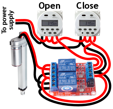
Here’s another method of wiring the timers that’s more straightforward. One timer opens the door & the 2nd timer closes the door. One event per timer … Simple, easy, inexpensive, & as reliable as the old way.
NOTE: Older CN101A timers may need the timer power wires swapped (reverse polarity).
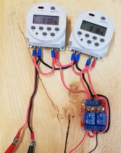
This new system uses a dual-SPDT relay module which replaces the DPDT relay in the old design.
Any 2-channel SPDT relay module with a high-level trigger should work. Typically there are 6 terminals on one side: NO/NC/COM for each relay, & 4 terminals on the other side: signal inputs for each relay (IN1/IN2), & power for the module (marked as +/-, or VCC/GND). There’s a jumper block to select the trigger type.
The timer wiring is the same as before — daisy chain power to each timer, & then to the module. Jump (+) to both NO terminals, and (-) to both NC terminals. Connect the actuator leads to the COM terminals. Run the output from each timer to the module’s IN1/IN2 terminals.
NOTE: Both trigger jumpers must be set to HIGH (outward setting). Apparently this relay is occasionally shipped with the jumpers set to LOW (inward), which would require different wiring from what I’ve shown.
YET ANOTHER NOTE: Sometime in 2016, these CN101A digital timers changed so the two power leads are reversed from how earlier CN101A timers work. I’ve updated the wiring diagram above to reflect this change, so now looking at the timers from the front, (-) is connected at the far left & (+) is 2nd in from the left.
Parts list:
- Dual-SPDT relay module
- (2) 12V programmable digital timers
- 12V linear actuator, 8″ extension, IP65 rated w/ built-in limit switches & mounting brackets from eBay (or get it on Amazon)
If you want a guillotine door instead of a swing door, get a 12″ extension linear actuator instead. Although around your chickens, maybe call it a “vertically sliding door”…
Power Supply Options
I’ve received several questions about my wiring diagram’s purposefully ambiguous “power supply”, so here are some different options.
 Solar panel: You can use a very low-watt solar panel connected directly to the battery with a fuse, so that the solar panel acts as a trickle-charger. The problem is the solar panel also slowly discharges the battery at night*, & so this system relies on whether the solar panel can generate more power during the day than it uses at night – normally not a problem, except if you live somewhere like I do without much sunshine in the winter.
* To prevent discharge you can add a blocking diode, but I’m not going to get into that (Google has your back) — the solar charge controller below is a better method for about the same price.
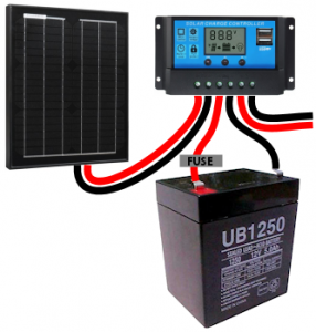 Solar panel w/ controller: This uses a solar charge controller which regulates power to the battery & automatically disconnects the solar panel at night. You can use any size solar panel, although panels over 20W are probably not necessary unless you are using a different system with a higher constant power draw (like a photocell) rather than the two timers.
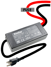 Dedicated power: If you have A/C power to your coop, you can use a 12V power adapter with an amp rating higher than the power draw of the linear actuator. This method is by far the least expensive, but if the power goes out, your chicken coop door won’t open/close.
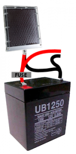
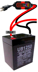 Dedicated power with battery backup: Nice method that handles power outages. With this system you need a trickle charger (“battery maintainer”), and a 12V battery with an amp rating higher than the power draw of the linear actuator. As with any battery, put a fuse on the positive lead coming off the battery.
So that’s it for power supply options. Here are some other useful notes:
Fuse sizing: Typically the fuse is rated 50% more than the maximum power draw of the linear actuator, so for instance if your linear actuator is rated for 5 amps max, use a 7.5-amp fuse. For a 6-amp linear actuator, use a 10-amp fuse.
Wire gauge: 16-gauge or 18-gauge wire should be fine, unless you are using more than a few feet of wire for some reason.
Wire connectors: I used spade terminals to connect wires to the timers & battery tabs. Keep in mind you’ll need to use a larger size terminal (than your wiring) when you splice 2 wires into one terminal. You can order a nice assortment of terminals on Amazon, or your local hardware store typically sells individual spade terminals from the small parts drawers.
Timer setup: First, set the time. Hold down the “clock” button & (still holding down “clock”) press D/H/M buttons to set day of the week, hour & minute.
Then press & release the “P” button. The number in the lower left shows the timer event number (1, 2, 3 etc) & whether you are setting the ON or OFF time for each event. So the first time you press “P” the timer shows “1” and “ON” in the corner — you are setting the start time for the first event. Press the H/M buttons to set the event start info. To have the event occur every day, make sure the display indicates “MO TU WE TH FR SA SU”. To change it, push the “D” button. When you’re done setting the event start info, press “P” again & set the same info for the event’s end time. Press the clock button when you’re done.
Example timer settings:
- Door open timer: start event 6:30AM, end event 6:31AM.
- Door close timer: start event 8:30PM, end event 8:31PM.
Final step is press the “Manual” button until you see “AUTO”. That means the timer is ready to be triggered by the events that you set up.
Press “Manual” whenever you need to override the timer. It cycles through AUTO -> ON -> AUTO -> OFF, so you may need to push the manual button several times to trigger ON. Remember to set the mode back to AUTO when you’re done — otherwise the events won’t trigger the timer.
The “C/R” button resets the time if you make a mistake setting up an event.
Manufacturer instructions for the CN101A timer are here.
Troubleshooting: If the actuator runs backwards, switch the actuator leads where they plug into the COM terminals. If the wrong timer controls the wrong event, switch the timer output leads either where they plug into the IN1/IN2 terminals or at the timers (doesn’t matter, same result). If a timer doesn’t switch at all, reverse power polarity to the timer (swap positive & ground). Also make sure the power supply has sufficient amps because otherwise the red light will come on but the timers won’t actually switch the circuit. If the timers don’t work when an event occurs (no red light & no “click” sound), make sure it’s set to AUTO mode — push the MANUAL button until you see AUTO on the display.
Wiring & testing the prototype.
Circuit Details: With neither timer activated, both motor leads are (-). With one timer/relay pair switched on, one lead switches to (+), the other stays (-) & the motor either runs forward or reverse. With both timers activated, both motor leads are (+) … that shouldn’t happen with your timers set properly, but it’s fine if it does (not a short circuit).
Don’t shoot the hobbyist: So far this design seems reliable. I’ve only had to replace 1 timer that stopped switching after 5 years of use.
Troubleshooting: See below for two videos that demonstrate normal operation of the relay & tips such as how to set the relay module trigger & test the relay.
Questions for electrical engineers:
- Does this module handle EMP from the actuator motor being switched off, or ideally should I add something to manage that? There are a bunch of other components on the circuit board in addition to the two relays, not sure what it’s designed to handle.
- I’ve come across this relay module used with IN1/IN2, NO1/NC2, & NC1/NO2 each jumped together, like this, which seems to provide the same exact function as a single DPDT relay wired as an H-bridge. To me this makes very little sense — essentially using two SPDT relays to accomplish the same function as one DPDT relay, but with more complicated wiring & greater possibility of component failure. Are there any benefits to this setup over a single DPDT relay?
- Is there any benefit to using a motor reversing solenoid over this 10-amp relay module (perhaps built-in handling of EMP)? Or are those solenoids just primarily designed to handle more amps & a longer duty cycle?
Happy chicken coop dooring. Any questions or comments, let me know!
If you use this automatic chicken coop door design in a video or blog post, please give a link or mention this blog post. Much appreciated.