Preface: if you already have a kegerator & want to add seltzer, all that’s stopping you is $60 in parts. See the section at the bottom of this post.
Dumb idea. Who wants 15 gallons of just one beer?
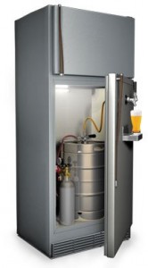
Most beer drinkers want a kegerator, which has obvious benefits: cheep beer, always cold, rarely runs out, no empties, access to beers you can only get by keg… bonus freezer space …
You buy beer in half-barrel kegs because per drink, it’s half the cost of bottled or canned beer. But there’s no sense having a huge half-barrel keg taking up your entire your kegerator, especially as it gets toward empty. Also there’s having to drink 15 gallons of just one type of beer & getting sick of it.
What you need is 4 soda or corny (originally, “Cornelius”) kegs. And a few other things. We’ll get to that. What you may not know is:
- For some variety, trade corny kegs with a neighbor/co-worker/relative, so you don’t have to drink 15 gallons of one beer yourself, thereby ruining your favorite beer.
- You can easily use the same CO2 system to make an endless supply of seltzer or soda. This blows away a Sodastream in all respects, especially price & carbonation.
The idea here is get a half-barrel keg, but transfer it off into three 5-gallon corny kegs. Use a 4th corny keg for seltzer. Corny kegs take up far less room in your kegerator fridge & are easier to manage.
The fridge
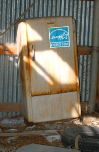
Use an energy-star rated fridge, from 2001 & newer if you can.
Chances are you already have an old fridge, so you’re not choosing what fridge to convert into your kegerator. If you do have a fridge choice, get a model with the freezer on the bottom, & one that maximizes corny keg space (see keg layout below). You can store beer kegs for a year or more, so some extra space for reserve kegs in your fridge is a good thing.
Some people don’t like the idea of an extra fridge because they think there’s a high electricity cost. That’s only true for refrigerators over 25 years old. Any fridge made this century is an energy-efficient model that will add $6/month. Older models from 15-25 years ago might burn through $10/month. The Energy Star website has a fridge energy cost calculator.
Keg layout
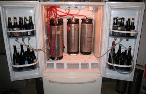
Best choice: a bottom-freezer fridge w/ room for 6+ corny kegs.
Figure out how many corny kegs will fit in your fridge. Take out all unnecessary bins, shelves, etc. Keep the fridge door bins if you can, since it’s nice to have storage for some bottled beer too. The door needs to close, so adjust your depth measurement for that. The plastic floor of your fridge is not meant for 50-lb point loads as you roll kegs around, so make a plywood floor insert to distribute the keg weight.
There are two types of corny keg connections: ball- & pin-lock. They’re equally good but the kegs are slightly different dimensions:
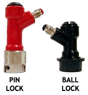
- Ball-lock: 8.5″ diameter, 25.75″ tall w/ couplers
- Pin-lock: 9″ diameter, 24″ tall w/ couplers
That minor difference can matter if space in your keg fridge is tight. Pin-lock kegs by themselves are shorter, but their couplers are taller. You can get a pin-lock keg down to 23.5″ tall (again, with couplers) using a ball-lock conversion kit.
Tap layout
Figure out how many taps you want, & the best place to locate them: the side, or the door. Few things to consider here…
Locating the taps on the sides:
- Coolant tubes. Find out where the coolant tubes are by running the fridge with the door open for a bit. Condensation will form on the interior walls showing you where the tubes are. On most fridges, the tubes are only in the back of the fridge & the sides are just foam, meaning you can put your taps pretty much anywhere. That said, don’t mess up. Hitting a coolant tube will instantly ruin your fridge.
- The taps will extend into the fridge compartment by an inch or two, so make sure there’s still room for your keg layout. If space is tight, the best place could be for the taps to go on the fridge door in between the bins.
- Determine where you’ll be drilling through on the inside & then mark the layout on the outside, or vice versa. Especially for taps located toward the back of the fridge, make sure you’ll be drilling into the fridge compartment & not into the radiator space.
Locating the taps on the fridge door:
-
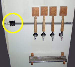
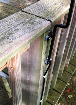
Fridge door link for long tap handles.
If you have a top-freezer fridge, either make a fridge door link (see photo) or locate the taps low enough on the fridge door so there’s enough room to open the freezer without hitting the tap handles. Short tap handles extend 5″ from the center of the tap holes to the top of the tap handle. Long tap handles can extend upwards of 12-18″, so in terms of pour height, long taps work better located on the sides of the fridge, or use the door link. For a bottom-freezer fridge, tap handle height isn’t a problem.
- Open the fridge door to see what you’ll be drilling through on the inside.
Regardless of the tap locations, you’ll need a flat or mostly flat surface on the inside of about 1.5″ diameter to tighten down each tap shank nut, which keeps your taps from spinning.
Tap details

Who knows, you might get this tap handle someday?
Next, tap shank length. The shank goes from the outside of the fridge to the inside. The tap faucet should stick out from the fridge so the tap handle (especially tall ones) can tilt back closed without hitting the fridge. I’d recommend getting at least 5″ long tap shanks. Whether or not you end up using long taps, it’s nice to have some space around tap handles, & it’s easy to make a wood spacer. More on that later.
For horizontal tap spacing, I’d wouldn’t go tighter than 3″ on center. Consider the available width on your fridge, your drip tray width, & future tap expansion plans. If you’re not ready to not put in your maximum number of taps right away, with tap spacing over 6″ apart, you can always add a tap in between later on.
Drip trays
There are two types, drain hole & no drain hole. Trays with a hole have to drain somewhere, like into a bucket — get these if your pouring style is to dump the first foamy half-pint down the drain. Drain trays are also good for amateur guest pourers who frequently overfill. Be warned though — with either style, mold will grow after a few weeks, & it stinks. No drain means limited spill capacity, & you’ll need to rinse it out more often — not necessarily a bad thing — and it looks cleaner, less like a science project.
Trays are available starting at 6″ wide & go up from there. Tap faucet spouts extend down a couple inches, so to fit most beer glasses, plan on locating the drip tray top at least 9″ below the tap holes’ center line … 12″ below is pretty common.
Minor detail: the drip trays will need to be mounted out from the fridge wall the same distance as the wood spacer you make for the taps.
 A caveat for beer super-snobs
This setup assumes you’re good with keeping your beers at one common pressure. Most beer drinkers are okay with this. If you seriously need your beers kept at simultaneously different pressures, this setup is not for you.
I’m buying what now?
Here’s the shopping list. Don’t get overwhelmed. You save $1 with each beer you drink! IMPORTANT: Kegs & couplers linked below are ball-lock.
- CO2 tank – $65 for 5-gal tank (empty), or rent from your local homebrew shop.
- Dual-pressure regulator (60 PSI max) w/ shutoff & check valves – $103
- 4-way manifold with shutoff & check valves – $50 (less & more valves available)
- Drip tray – $24 for 6″ no drain wall-mount, or $24 or $16 for a 19″ no drain stainless that requires shelf or glue mount. eBay, MoreBeer.com & BeverageFactory.com are good sources for more drip trays.
- D-style keg coupler – $26
- Air tubing, 12′ of clear 5/16″ ID – $10
- Beer tubing, 100′ of clear 3/16″ ID – $55 – each tap requires ~15′, & with this large roll you can just replace tubing rather than using strong chemical beer line cleaners.
- Beer line (5′) with ball-lock coupler & party tap – $14
- Beer line tail piece fitting – $3
- Quick disconnect set – $15 each, get two
- Male quick disconnect – $7 each, get two
- 11 hose clamps (1/4″ to 5/8″ range) – $4 for a 10-pack. Get two packs since you’ll need more for your taps – see below.
- Spray bottle – $3
- Sanitizer, 32oz – $16 for iodine-based or $24 for acid-based Star San
- PBW cleaner, 1lb – $9
- Keg lube – $5
- O-ring kit for corny kegs – $3 – just in case.
If you aren’t putting in your maximum possible number of taps right away, get a manifold with more valves than you might use at first. This makes future expansion easy, & just leave the extra valves shut off. With a 4-valve manifold you can have 4 beer taps with a shared line for keg transfers, or 3 beer taps plus a dedicated transfer line. Also, most manifolds have a pass-through port on the end so you can always add another manifold later on.
For each tap, you’ll need:
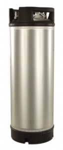
A new keg. My precious.
- Ball-lock corny keg – $120 new, or ~$60 (used) on eBay, or try Craigslist.
- Perlick 630SS stainless tap faucet – $40
- 5″ stainless tap shank w/ nipple assembly – $22
- Air tubing assembly (5/16″ ID clear) w/ ball-lock air coupler & hose clamps – $9
- Ball-lock beer coupler – $5
- 2 hose clamps (for beer line)
- Tap handle – $2 for a plastic handle, or the sky is the limit on eBay, buy them direct from your favorite breweries, or make your own.
The new kegs from MoreBeer.com are amazing, made in Italy & shipping is free! Granted you can save a lot with used kegs, but be prepared to deal with cleaning soda syrup residue, leaky O-rings & other light keg maintenance — no big deal & O-rings are cheap, but used kegs are just not as easy, or as shiny.
If you need to cut costs, you can find a chrome-plated tap & shank combo for half the price of stainless, like this one (2 taps with 2 shanks for $57).
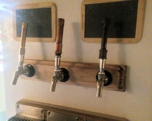
Side taps. The wood spacer allows for taller tap handles.
The 5″ tap shanks are likely much longer than necessary to get through your fridge wall, so you’ll need to make a wood spacer for the outside of the fridge. The benefit is you can use long tap handles — the spacer creates enough room so the tap handles can reach shut-off position without hitting the fridge. Cut & stack thin boards together until you get the thickness you need. Hardwood scraps work great, especially flooring, or pine 1x4s. If you don’t want the option of using fun long tap handles (what’s wrong with you!), get shorter shanks — whatever length is just long enough to get through your fridge wall.
A 5-gallon CO2 tank should last around 6 months, depending on how much you drink. I usually go through something like 2 half-barrel keg transfers & serve 4 kegs of beer & 4 kegs of seltzer. Seltzer is at a higher pressure, so it takes more CO2 per keg. Eventually consider getting a spare CO2 tank, because it sucks when you run out & can’t pour beer.
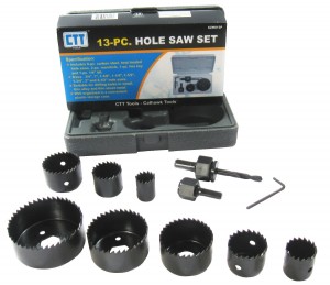
Get the hole saw set. Works much better than ruining spade bits.
Tools required
- Saw (for wood – jigsaw, handsaw, etc)
- Knife
- Power drill
- Tape measure
- Crescent wrench
- Regular screwdriver
- 3/4″ & 1″ hole saws – $13 for a 13-piece set
- Tap wrench – $3
- Round metal file (optional)
When pushing beer or air tubing onto a barbed fitting, first dunk the tubing in a cup of very hot water for a minute or two to soften the tubing. Otherwise it’s basically impossible.
Setting up the CO2
- Get your CO2 tank filled at your local homebrew supply, welding supply, etc.
- Determine a good place for the CO2 tank outside the fridge & make a bracket or strap for it so it can’t fall over. Also decide where to put the air manifold, probably outside the fridge again. Mounting it on a board makes things easy. If you do put the manifold inside the fridge, that means less drilling (only requires 1 hole for the CO2 supply hose) but definitely put the manifold in front near the door, not behind any kegs.
- Screw the regulator onto the CO2 tank. It’s a rubber gasket, so don’t overtighten & don’t use teflon tape. Close the inline shutoff valves below the regulators, then open the main tank valve. Turn the pressure adjustment knobs on each regulator to set one at ~12 PSI (beer), & the other at ~40 PSI (seltzer). If you turn a knob to decrease pressure, bleed off the excess by opening the inline shutoffs very briefly to bleed off the excess pressure & see the reading change.
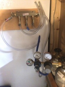
CO2 tanks & manifold with shutoff valves.
- Find a good spot for the air hoses for each tap to pass into the fridge, where hoses won’t get in the way of your keg layout. Drill holes for the air hoses. Don’t hit any coolant lines. Use a 5/8″ drill bit or hole saw, or a 3/4″ hole saw. 3/4″ is larger than the air tubing, but it won’t matter after you seal them. Dull any razor-sharp edges with a metal file or screwdriver.
- Run air hoses for each tap through the holes you drilled. These air lines run from the manifold valves for as many beer taps you’re putting in, & also one air line directly from the seltzer regulator. Tape the ends of the hoses as you push them through so you don’t get fridge foam crud in them. Seal around the holes with silicon sealant.
- Cut air hoses to an appropriate length, & attach the air couplers to the hose ends inside the fridge (if they didn’t come preassembled) — just don’t make the air tubing too short. The air couplers are harder to push onto the kegs once the air lines & kegs are pressurized. If vertical space is tight, leave enough tubing so you can push couplers onto kegs just outside the fridge where it’s easy & then set the kegs back into the fridge. Label the air hoses #1 #2 etc at the valve end & also at the coupler end.
- Check for leaks — pressurize the system with the regulator & manifold valves open, then turn off the tank valve & check the pressure gauge after ~15 minutes. It should not read zero.
If you have a leak, spray soapy water on all the CO2 fittings. Try around the regulators first since that’s high-pressure, especially the threaded metal fittings on the regulators & manifold.  If threaded fittings are leaking, try tightening them & if that doesn’t work, you’ll need to take them apart, clean off the old teflon tape, wrap on new teflon tape & retighten. Also repeat the pressure test with the manifold valves closed. If that fixes the leak, it’s either the check valves directly below the shutoff valves (retighten or re-teflon & tighten), or the keg couplers are leaking around the pin that’s up inside the coupler. That’s fine since they will be on beer kegs, & what matters is the O-ring seal on the keg poppet. Remember to shut off manifold valves for any CO2 supply lines you aren’t using.
If you have an extra valve at the manifold that you’re not using for beer taps, save it for a dedicated air line to the D-style coupler for transfers — that one doesn’t go into the fridge. Or if you’d rather use all your manifold outlets for taps, that’s okay — you’ll set up one tap air line as a dual-purpose keg transfer air line, using a quick disconnect. More on that later.
Setting up the taps
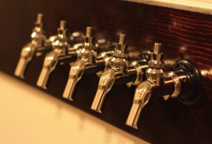
So pretty. So shiny. So much potential.
- Drill your tap holes. A few simple words, but such a big step. There are many things to consider here … intrusion into your keg layout, faucet spacing, pour height, tap handle clearance, drip tray … By now you’ve worked all this out, right? Right. Once again, don’t hit any fridge coolant lines. Use the 1″ hole saw. Or you can use (ruin) a 1″ spade bit, but it’s not pretty. The tap shanks are actually 7/8″ diameter but if you drill the holes at 1″, you’ll have less trouble getting the faucets aligned nicely.
- Install the tap shanks through the holes. They should extend into the fridge interior as little as possible — which means creating a wood spacer for the outside of your fridge & drilling the tap shank holes through that as well. This will help get the taps away from your fridge enough so you’ll have room for long tap handles. Tighten the shank nuts.
- Put the taps on! Use the tap spanner wrench. If you didn’t get one, use vice grips with leather or thick cloth pieces in the jaws so it doesn’t scratch your precious shiny taps. Don’t overtighten.
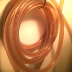
Coil your beer tubing or it’s a giant unruly mess.
- Cut your beer tubing to length. There’s a whole science devoted to determining beer line length to get the correct PSI at the tap, which affects foam. Ignore anything that says 3/16″ tubing drops 2-3 PSI per foot — it’s not a linear equation & far more complicated than that. Plan on 12-15′ of beer tubing per tap or if you want to get exact about it, smart physics-PhD-type people have you covered.
- Connect your beer tubing from the tap shanks to your (beer) keg couplers.
Setting up the transfer system
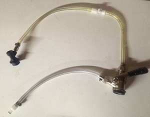
The transfer system (short air hose for photo purposes only).
American beers typically come in kegs with a Sankey “D”-system valve. To transfer it you’ll need a beer line that goes from a D-style coupler to a corny keg coupler. You’ll also need a CO2 line to the D-style coupler, either directly from the manifold, or you can set up a dual-purpose CO2 supply using one of the tap air lines. Either way, use the leftover 9′ section of air tubing — it’s probably longer than you need but you can cut it down once you figure out what length is convenient.
-
- If you are going with a dedicated air transfer valve from the manifold, attach the 9′ air hose on to the manifold valve. Cut the air hose a few inches away & install a quick disconnect where you made the cut, with the female end toward the manifold & the male end on the long section of hose.
- If you’re dual-purposing a tap air line as the transfer air supply, cut one of the 5′ air line assemblies about a foot from the keg coupler end. Put a quick disconnect on that, with the female end toward the manifold & the male end toward the keg coupler. Then put a male quick disconnect on the 9′ section of air hose.
- Attach the other end of the 9′ air hose to the D-style coupler to the barbed fitting, usually labelled “GAS IN”, that’s at an angle.
- Take your “Beer line with ball-lock coupler & party tap” & cut the line in half. Remove the beer tubing on the party tap end & save it for the next step — even at 5′ length, it’s far too short to prevent foam. Instead, cut ~12′ of beer line from your bulk roll & put that onto the party tap instead. Put male quick disconnects on both the party tap hose & the keg coupler hose.
- Take the short leftover beer line from the last step & attach one end to the D-style coupler using the beer line tail piece fitting, & put a female quick disconnect on the other end.
Sanitize your kegs
If your kegs are really dirty, scrub with dish soap & rinse. For used kegs, you may also need to take off the poppets with a socket wrench to clean them too (search YouTube for help). Add cleaner per the instructions on the container & let sit. This can take 24 hours with some cleaners. Rinse when done. Lube the gaskets with keg lube.
Mix appropriate amounts of sanitizer & shake for an appropriate amount of time. I do about 2 minutes but read the instructions. I prefer iodine-based sanitizer because it’s very effective but not harmful chemicals. Some people prefer Star San. To each his own.

Pro tip: Do not spray sanitizer in your eyes.
Do sanitizing with the keg slightly pressurized — hot tap water will heat up the air inside the keg & usually does the trick, or add a bit of CO2 — that lets you run sanitizer out the IN (with keg upside down) & OUT (keg upright) poppets by pushing the pin down with a highly technical tool, like a fork. Do not spray sanitizer in your eyes. Run some through the pressure relief valve (keg upside down) too.
Most people don’t open their kegs after the sanitizer step, & both Star San & iodine-based sanitizers don’t need a rinse — read the labels. Watch YouTube videos if you need more help. Don’t leave the keg open if you rinse it, so bacteria & other contaminants can’t get in.
Partially pressurize your empty sterilized keg, but not all the way or you’ll waste a lot of CO2. This will help you check the seals & also slows down the beer as it starts transferring, which prevents foaming.
Last step is to mix up some sanitizer solution in a spray bottle. Spray all the couplings & keg poppets.
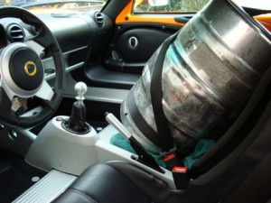
Do whatever it takes to get the keg home safely.
The first beer transfer
Get a half-barrel keg. Treat it like a sleeping baby, no shaking, bumping or dropping it. That creates foam, ENEMY OF BEER. Also, keep it cold, because again with the foam.
Ready for a drink? Okay, but pay attention here because the order matters. Do it wrong & the beer can backflow up the air line.
- Clean the half-barrel keg’s D-fitting with your sanitizer spray bottle.
- Connect your CO2 supply line to the D-coupler.
- Turn on the air valve at the manifold — either the dedicated line, or the dual-purpose tap line depending on how you set it up.
- Connect the D-coupler to the party tap — press the quick disconnect until it clicks. Make sure the party tap is closed. If it’s open, beer will start pouring out in the next step.
- Connect the D-coupler to the half-barrel keg — twist clockwise until it stops (turn firmly but not hard), then push down the handle until it clicks.

Cheers. Nice work.
Pour off a pint or two. Cheers. The half-barrel is 15.5 gallons & 3 corny kegs fit 15 gallons. So you have at least 4 pints to drink, or store in a growler if you must.
Okay, ready for the keg transfer.
- Disconnect the party tap from the D-coupler, & connect the ball-lock coupler. Have some paper towels handy, because the quick disconnects will drip a bit.
- Connect the ball lock coupler to your sanitized keg’s OUT poppet.
Beer will start flowing from the half-barrel keg to your corny keg, backfeeding down the OUT tube into the bottom of your keg. Every few minutes, pull the pressure relief valve for a second or two, not too much or the beer will foam & filling your keg full will take MUCH longer. Keep going until foam starts shooting out the relief valve when you pull it.
Get a bathroom scale & put the keg on it. When it hits ~51.5 lbs, it’s full. Anything less & you need to wait 20-30 minutes. This is an excellent time to have another pint, & start filling another keg. By then the foam will settle & you can try topping it off more.
Eventually you’ll hear the bubbling sound of your half-barrel keg going empty.
Clean up
 Remove the D-coupler from the half-barrel keg & the corny keg coupler from the corny keg.
- Disconnect the transfer air & beer lines at the quick disconnects.
- Connect the party tap to the D-coupler & open the party tap to bleed off the residual pressure in the beer line.
- With the party tap still open, push the D-coupler handle down, turn it upside down & run tap water through the D-coupler & out the party tap, then run some sanitizer solution through it, then drain it.
- Disconnect the party tap & attach the ball-lock coupler. Push in the bottom of the ball-lock coupler — this can be a little hard — use the sanitized head of a small screwdriver. Run more water & sanitizer through the D-coupler, & drain the lines again.
- Put the whole transfer setup away somewhere clean, ready for your next keg transfer.
- Tag your corny kegs with the beer details & transfer date.

Congrats.
Final beer setup
Make sure your air lines are pressurized. Connect your CO2 & beer lines to the kegs you’re tapping (close taps first) & put everything into the fridge. Check for beer leaks & make sure the fridge door shuts all the way. Pour beer out the taps. Drink. Be merry. Have parties. Enjoy your awesome new beer drinking experience.
Check for beer leaks again in a few hours, just in case.
ONLY CONNECT A CO2 LINE TO A KEG WITH THE MANIFOLD VALVE SWITCHED ON, SO THE CO2 LINE IS PRESSURIZED. Better yet, connect the liquid line first & pour a glass, then connect the pressurized CO2 line. Kegs can build up pressure while sitting. Pouring off beer before hooking up the CO2 reduces keg pressure & prevents backflow up the air line. Some keg couplers don’t have an integrated check valve (backflow preventer). Even when they do, they don’t always work.

What about the seltzer?
Oh, right. The seltzer. Fill a sanitized keg with tap water. Hook up your 40 PSI CO2 line, shake the keg for 10 minutes, & put it in the fridge. Come back & start drinking seltzer in a few days. For faster carbonation, get a carbonation stone ($6).
TL;DR
Go buy a 6-pack.
I’m bored, what else can I do?
Build a keezer. It’s a kegerator made from a chest freezer. More room for more kegs!
Already own a kegerator & just want to add a second seltzer regulator?
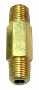 Get another primary regulator ($55) that can handle up to 60 PSI & has a shutoff AND a check valve. Then buy a 1/4″ MPT LHT coupler ($5) or if that’s out of stock, try here. This setup works better than secondary regulators with no chance for cross contamination.
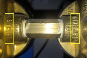
Threading info on the regulator housing.
The LHT (left-hand thread) adapter will handle the typical CO2 regulator thread setup. Check your regulator threads to be sure — check the housing, or you can tell by looking at it: which way would something twist when being screwed in? Clockwise = RHT, Counterclockwise = LHT.
Remove the pressure gauge from your old regulator & remove the tank inlet from your new regulator. Thread the two regulators together using the adapter with teflon tape. Set the new regulator at 40 PSI, clean & fill a keg with water, hook it up to your seltzer CO2 line, shake the keg for 10 minutes to give it a head start, & wait a few days for full seltzer carbonation. For faster carbonation, get a carbonation stone ($6).


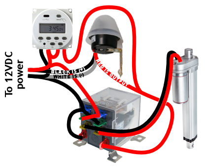
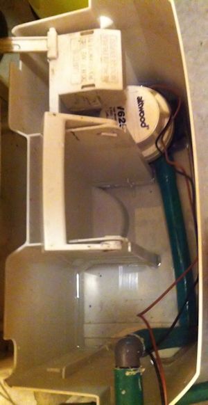
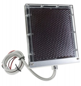
 Solar panel: You can use a very low-watt solar panel connected directly to the battery with a fuse, so that the solar panel acts as a trickle-charger. The problem is the solar panel also slowly discharges the battery at night
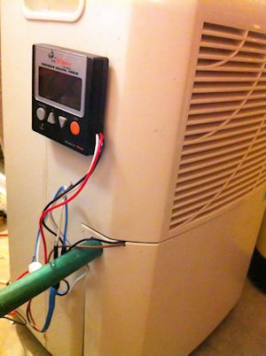
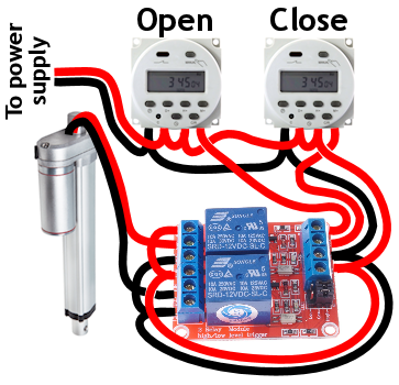
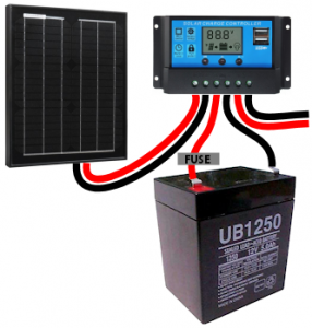 Solar panel w/ controller: This uses a solar charge controller which regulates power to the battery & automatically disconnects the solar panel at night. You can use any size solar panel, although panels over 20W are probably not necessary unless you are using a different system with a higher constant power draw (like a photocell) rather than the two timers.
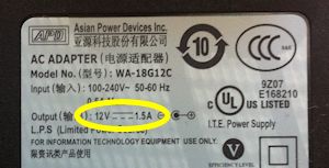
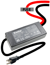 Dedicated power: If you have A/C power to your coop, you can use a 12V power adapter with an amp rating higher than the power draw of the linear actuator. This method is by far the least expensive, but if the power goes out, your chicken coop door won’t open/close.
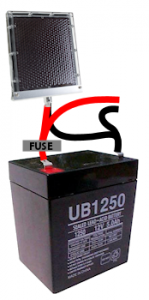
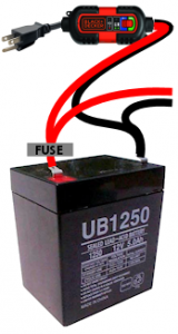 Dedicated power with battery backup: Nice method that handles power outages. With this system you need a trickle charger (“battery maintainer”), and a 12V battery with an amp rating higher than the power draw of the linear actuator. As with any battery, put a fuse on the positive lead coming off the battery.
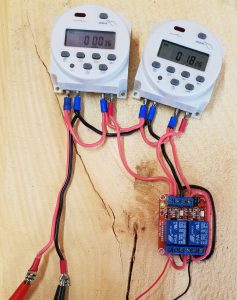

 Drobo makes a nice backup system, but the cooling fans are crap. The fan in my Drobo 5N was no exception & failed after 3 years, most of which it spent on standby with the drives spun down. As far as I know, the Drobo cooling fan runs constantly even when the drives are spun down.
 Unscrew 4 screws total, on the sides at the fan end: 1 upper & 1 lower screw. Leave all the other screws in place. Trust me on this.


 When we first got our chickens, each night I’d walk up to the coop & close them in. That worked great until the night I’d fall asleep putting our 3 kids to bed, or start watching a late-night movie, & suddenly OOOOHH SHIT, THE CHICKENS!!! …followed by a guilty run to the coop, wondering if I was about to find sleepy hens or a poultry massacre.
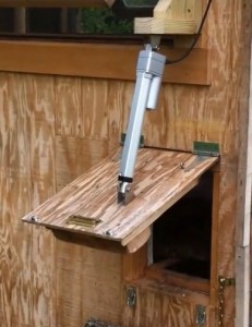
 To recharge the battery, I used a small 1.25-watt 12V solar panel. Since the panel’s power output is so low, it acts as a trickle charger, & that way you may not need a solar charge controller as long as the panel is in direct sunlight for most of the day. I’d still recommend a charge controller to make sure the panel doesn’t have a net drain effect on the battery in winter or other low-light conditions.
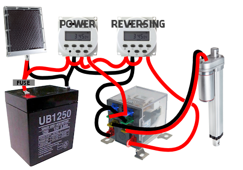
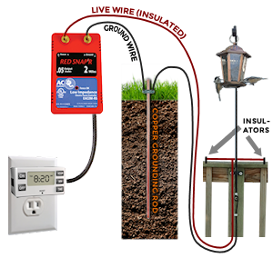
 I went with method #2 because the deck railing wires go flat on the railing & I liked how subtle that looked. The hard part is then the feeder hanger needs to be insulated from the deck & can’t touch the screws. I widened the mounting holes to fit short pieces of rubber (beer) tubing inside, & put the screws back through the tubing. I used a rubber spacer & flat washer on the screw head end, & a plastic spacer of 1/2″ PEX water line (which fit nicely over the beer tubing) to hold the feeder hanger away from the deck.
 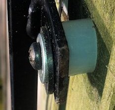 Then I drilled another hole in the hanger & used a small bolt to attach the live wire. I ran a loop of ground wire on top of the railing with fence staples.
 Last year we bought a shiny new Whirlpool fridge, french-door style with the bottom freezer. Eight short months later, water started leaking out the bottom of the freezer & pooling onto the floor. Apparently it had been leaking for awhile because when I pulled the fridge out, I found the water had been draining toward the back wall, quietly warping our hardwood floor. We don’t have the icemaker hooked up so it was definitely a defrost problem, caused by a little drain grommet. Thanks for nothing, Whirlpool.
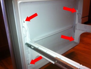 Step 2: Freezer door. It’s 4 screws, one in each corner. Just loosen them a few turns — don’t take the screws out entirely — it’s much easier putting the door back on when the screws are already in place. The door slides up & off.
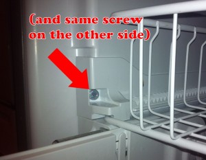 Step 4: Upper basket. Remove the 2 screws at the front of the rails, then lift up the rails slightly on each side, to slide the basket forward.
 On the plastic pieces at the back sides of the upper basket, push in two tabs with your screwdriver on each piece & pop them up. This will let the upper basket slide out off the rails.
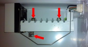 Step 5: Icemaker. Remove the lower screw, then loosen or remove the two screws above the icemaker. Unplug the wire harness where it passes through the rear panel — squeeze the sides of the plug & pull. Lift the icemaker up & out. The water tube will slide out of the guide.
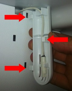 Step 6: Plastic guards. The thermostat guard is the skinny piece to the upper right. Push in (to the right) the tab on the left side in the middle. The guard opens like a door pivoting on the right edge, & pulls out.
 Step 7: Freezer panel. Remove the 4 screws in each corner. Push the thermostat back through the slot at the top, & also push the icemaker plug back through its slot.
 The drain hole is near the front of the rear tray in the middle. It’s pretty wide (1/2″) & short, only ~2 inches long. It goes straight down into a rubber “duck bill” grommet that’s probably plugged up with gunk, that you access from the back of the fridge…
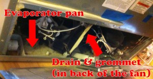
 Step 9: Drain grommet. Pull out the fridge so you can access the back side. Remove the screws (6?) around the lower access panel, pop the power cord up & tilt the panel out of the way. The plastic tray under the fan is the evaporator tray — that’s where the water SHOULD normally be dripping into & evaporating from.