
UPDATE: I’ve also posted instructions for an automatic chicken coop door using a photocell with an optional timer override. However it consumes more power & the photocell may not be as reliable, so if that’s a concern, use the two-timers method below.
UPDATE II: For coops with AC power, there’s a 3rd method where the automatic coop door uses a Solar Time Table switch.
In March 2015 I posted a method for making an automatic chicken coop door using two timers & a DPDT relay, but the timer setup was complicated — one timer provided power, while the 2nd timer controlled reversing polarity & had to turn on simultaneously with the power timer. Not easy.
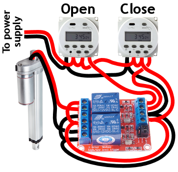
Here’s another method of wiring the timers that’s more straightforward. One timer opens the door & the 2nd timer closes the door. One event per timer … Simple, easy, inexpensive, & as reliable as the old way.
NOTE: Older CN101A timers may need the timer power wires swapped (reverse polarity).
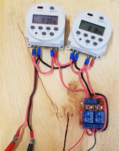
This new system uses a dual-SPDT relay module which replaces the DPDT relay in the old design.
Any 2-channel SPDT relay module with a high-level trigger should work. Typically there are 6 terminals on one side: NO/NC/COM for each relay, & 4 terminals on the other side: signal inputs for each relay (IN1/IN2), & power for the module (marked as +/-, or VCC/GND). There’s a jumper block to select the trigger type.
The timer wiring is the same as before — daisy chain power to each timer, & then to the module. Jump (+) to both NO terminals, and (-) to both NC terminals. Connect the actuator leads to the COM terminals. Run the output from each timer to the module’s IN1/IN2 terminals.
NOTE: Both trigger jumpers must be set to HIGH (outward setting). Apparently this relay is occasionally shipped with the jumpers set to LOW (inward), which would require different wiring from what I’ve shown.
YET ANOTHER NOTE: Sometime in 2016, these CN101A digital timers changed so the two power leads are reversed from how earlier CN101A timers work. I’ve updated the wiring diagram above to reflect this change, so now looking at the timers from the front, (-) is connected at the far left & (+) is 2nd in from the left.
Parts list:
- Dual-SPDT relay module
- (2) 12V programmable digital timers
- 12V linear actuator, 8″ extension, IP65 rated w/ built-in limit switches & mounting brackets from eBay (or get it on Amazon)
If you want a guillotine door instead of a swing door, get a 12″ extension linear actuator instead. Although around your chickens, maybe call it a “vertically sliding door”…
Power Supply Options
I’ve received several questions about my wiring diagram’s purposefully ambiguous “power supply”, so here are some different options.
 Solar panel: You can use a very low-watt solar panel connected directly to the battery with a fuse, so that the solar panel acts as a trickle-charger. The problem is the solar panel also slowly discharges the battery at night*, & so this system relies on whether the solar panel can generate more power during the day than it uses at night – normally not a problem, except if you live somewhere like I do without much sunshine in the winter.
* To prevent discharge you can add a blocking diode, but I’m not going to get into that (Google has your back) — the solar charge controller below is a better method for about the same price.
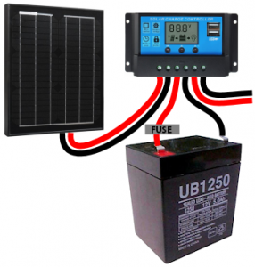 Solar panel w/ controller: This uses a solar charge controller which regulates power to the battery & automatically disconnects the solar panel at night. You can use any size solar panel, although panels over 20W are probably not necessary unless you are using a different system with a higher constant power draw (like a photocell) rather than the two timers.
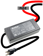 Dedicated power: If you have A/C power to your coop, you can use a 12V power adapter with an amp rating higher than the power draw of the linear actuator. This method is by far the least expensive, but if the power goes out, your chicken coop door won’t open/close.
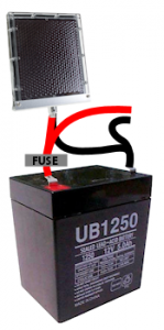
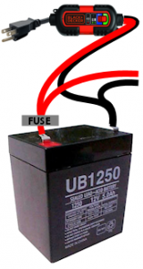 Dedicated power with battery backup: Nice method that handles power outages. With this system you need a trickle charger (“battery maintainer”), and a 12V battery with an amp rating higher than the power draw of the linear actuator. As with any battery, put a fuse on the positive lead coming off the battery.
So that’s it for power supply options. Here are some other useful notes:
Fuse sizing: Typically the fuse is rated 50% more than the maximum power draw of the linear actuator, so for instance if your linear actuator is rated for 5 amps max, use a 7.5-amp fuse. For a 6-amp linear actuator, use a 10-amp fuse.
Wire gauge: 16-gauge or 18-gauge wire should be fine, unless you are using more than a few feet of wire for some reason.
Wire connectors: I used spade terminals to connect wires to the timers & battery tabs. Keep in mind you’ll need to use a larger size terminal (than your wiring) when you splice 2 wires into one terminal. You can order a nice assortment of terminals on Amazon, or your local hardware store typically sells individual spade terminals from the small parts drawers.
Timer setup: First, set the time. Hold down the “clock” button & (still holding down “clock”) press D/H/M buttons to set day of the week, hour & minute.
Then press & release the “P” button. The number in the lower left shows the timer event number (1, 2, 3 etc) & whether you are setting the ON or OFF time for each event. So the first time you press “P” the timer shows “1” and “ON” in the corner — you are setting the start time for the first event. Press the H/M buttons to set the event start info. To have the event occur every day, make sure the display indicates “MO TU WE TH FR SA SU”. To change it, push the “D” button. When you’re done setting the event start info, press “P” again & set the same info for the event’s end time. Press the clock button when you’re done.
Example timer settings:
- Door open timer: start event 6:30AM, end event 6:31AM.
- Door close timer: start event 8:30PM, end event 8:31PM.
Final step is press the “Manual” button until you see “AUTO”. That means the timer is ready to be triggered by the events that you set up.
Press “Manual” whenever you need to override the timer. It cycles through AUTO -> ON -> AUTO -> OFF, so you may need to push the manual button several times to trigger ON. Remember to set the mode back to AUTO when you’re done — otherwise the events won’t trigger the timer.
The “C/R” button resets the time if you make a mistake setting up an event.
Manufacturer instructions for the CN101A timer are here.
Troubleshooting: If the actuator runs backwards, switch the actuator leads where they plug into the COM terminals. If the wrong timer controls the wrong event, switch the timer output leads either where they plug into the IN1/IN2 terminals or at the timers (doesn’t matter, same result). If a timer doesn’t switch at all, reverse power polarity to the timer (swap positive & ground). Also make sure the power supply has sufficient amps because otherwise the red light will come on but the timers won’t actually switch the circuit. If the timers don’t work when an event occurs (no red light & no “click” sound), make sure it’s set to AUTO mode — push the MANUAL button until you see AUTO on the display.
Wiring & testing the prototype.
Circuit Details: With neither timer activated, both motor leads are (-). With one timer/relay pair switched on, one lead switches to (+), the other stays (-) & the motor either runs forward or reverse. With both timers activated, both motor leads are (+) … that shouldn’t happen with your timers set properly, but it’s fine if it does (not a short circuit).
Don’t shoot the hobbyist: So far this design seems reliable. I’ve only had to replace 1 timer that stopped switching after 5 years of use.
Troubleshooting: See below for two videos that demonstrate normal operation of the relay & tips such as how to set the relay module trigger & test the relay.
Questions for electrical engineers:
- Does this module handle EMP from the actuator motor being switched off, or ideally should I add something to manage that? There are a bunch of other components on the circuit board in addition to the two relays, not sure what it’s designed to handle.
- I’ve come across this relay module used with IN1/IN2, NO1/NC2, & NC1/NO2 each jumped together, like this, which seems to provide the same exact function as a single DPDT relay wired as an H-bridge. To me this makes very little sense — essentially using two SPDT relays to accomplish the same function as one DPDT relay, but with more complicated wiring & greater possibility of component failure. Are there any benefits to this setup over a single DPDT relay?
- Is there any benefit to using a motor reversing solenoid over this 10-amp relay module (perhaps built-in handling of EMP)? Or are those solenoids just primarily designed to handle more amps & a longer duty cycle?
Happy chicken coop dooring. Any questions or comments, let me know!
If you use this automatic chicken coop door design in a video or blog post, please give a link or mention this blog post. Much appreciated.
Tom
Hello again Wick, Well after about 7 tries I finally got a working set of electronics using the photocell instead of the timers. Couldn’t have done it without all your instructions and attention to detail on your project.
So now I am on to the construction phase and that should go by fairly uneventful.
I know there was a concern for the buzzing sound of the switch when the light is right on the edge of being where you need it to be but looking through the reviews on the part in Amazon, I found a comment that says to place a 30k OHM resistor between the #5 and #7 pins on the Op Amp. ( I’m probably going to eventually try this but it is the least of my worries… a little buzzing I can handle)
My main concern is what you brought up about the constant battery drain from the photocell. My possible solution to this is to try an Adjustable Repeat Timer Delay Relay. My thinking on this is this: if I splice the line out1 and out2 from the photocell individually to 2 separate delay relays that I can adjust the time to allow energy to flow though the system for 1-2 minutes allowing for the functioning of the actuator but after that time, the delay relay will disconnect the flow of energy until another cycle begins.
(When the energy from out1 , opening the door, is complete the energy to the control module is cut. When out2 initiates, out1 is no longer energized and the delay relay resets itself waiting for the out1 to energizes itself again starting the cycle all over again.)
I would add a picture of the wiring but I do not know how to do that in this blog…
Thoughts….
Wick
Hi Tom, that’s great you got it all working. I agree that delay timer method you described to cut power to the actuator relay(s) is probably the best method in terms of handling the power drain. A few months ago I bought some programmable timer modules — the 18 available timer modes sounded promising! I’m thinking there’s probably a way to handle it with just one timer module but again haven’t had time to sit down & try it out yet… Luckily, winter is coming 🙂
Which photocell are you using?
Tom
uxcell® DC 12V Photoelectric Switch Sensor Relay Module 50mmx25mm w 2 Cable (from Amazon).
Wick
Okay, that module has a built-in Songle SRD-12VDC-SL-C relay. I think this is the right data sheet – looks like the relay coil power draw is just under 0.5 watts. I wonder if there’s a photocell that uses less power — maybe one that doesn’t use a relay, or a latching relay that only requires momentary power to the coil…
Isaiah
Hi Tom, did your delay timer on the photocell work? I am also interested in finding a way to reduce the constant draw of battery power that comes with using a photocell and thought a delay timer might do the trick?
John Greene
I am interested in building one of these for use when I am out of town. This looks far better than the ready made versions I have seen on Amazon. Where can I get a list of parts and where to buy?
Wick
Hi John, thank you — I’ve added the parts list to the post.
Laura
novice here but where does the solar play into new model here?
Wick
Hi Laura, I wrote more about the “power supply” including 2 options for solar power.
dave
Hi,
I ran across your blog after researching a way to open/close a ceiling vent using a linear actuator. I am searching for a simple way to slide a insulated foam board back and forth to open/close a vent to my whole house fan. My question is would I be able to use a on/off light switch in place of the timers? When the actuator fully extends/retracts does it turn off or continue to drain power?
Wick
Hi Dave, an ON/OFF switch — single pole single throw (SPST) — wouldn’t work, but a DPDT switch like this ON/ON switch or this ON/OFF/ON switch will work great & you don’t need the relay module. You’d run positive/negative power to the center switch terminals & then run the linear actuator leads in an “X” to the terminals at opposite corners, like this.
The 3-position ON/OFF/ON switch I linked to stays in position, so in other words if you switch it ON, you can take your hand away & it stays ON. The linear actuator has built-in limit switches so it cuts power to the actuator motor automatically when the arm is fully extended/retracted (so to answer your question, there’s no power drain). If you’d prefer the switch to automatically return to OFF, you’ll want a momentary DPDT switch. However because of the limit switches you don’t need a momentary switch & in fact it would probably be less convenient since you’d have to push the switch for the ~20-30 seconds it will take for the vent to close. I think the simple ON/ON switch might work best.
Steve
Hello. Not sure if it matters but what Guage wire did you use? Also what connectors were used? Thanks
Wick
Good questions — I’ve updated this post with info about wire size & more about the connectors.
Quintin Bryant
I have a free linnear accuator from a bed frame that I’d like to use for a chicken coop door with this set up. It is a 24V and is way overkill I know, but hey free parts! Would I be able rig this up with your set up above?
Wick
Sure, it gets a little more complicated but still possible. Basically you’d separate the 12V power supply necessary for the timers & the relay coils from the motor circuit switched by the relay module. In the wiring diagram, see the red/black wires that loop from one end of the relay module to the other? Instead of doing that, you would connect your 24V power supply to the NO/NC terminals in the same way as described, but power would be from your 24V power supply rather than looping 12V power in from the relay module’s DC+/DC- terminals.
The relay module can handle 30VDC/10amps so it should be able to switch your 24V actuator just fine as long as it doesn’t draw more than 10 amps. Even if your actuator motor is rated for more amps, it likely won’t draw that much unless the door is hard to close.
You could also see if your actuator motor will run on 12VDC. Chances are it will, but would be 1/2 as powerful.
Hope that helps, good luck!
Joyce
Hello there,
We are wondering why we need a relay at all with one timer opening in the morning and one timer closing in the evening?
Wick
Hi Joyce, the only timers I’ve seen available are SPST, meaning they only switch one wire (“single pole”), & only on or off (“single throw”).
So with SPST switches, the (-) wire needs to be connected permanently & the timer controls (+). However since for each timer you need +/- connected opposite from each other (to reverse the polarity to the motor), that forms a short circuit when any timer is activated.
Lee
Wick, Thanks for the great post. I have wired all components as you depict in your drawing but neither timer is causing a movement of the linear actuator. The timers and the SPDT are getting power. I tested the linear actuator straight to the battery and it works fine. The only thing I can guess is the testing picture you posted and the drawing do not seem to correlate…maybe I can’t zoom in far enough on the picture though. Any thoughts would be appreciated. Thanks, Lee
Wick
Hi Lee, sorry for the delay there. Can you hear the relay switching? If it’s working it will make an audible clicking sound & if you put your finger on the relay you will feel it as well. If it’s still not working, can you post a photo?
Michael
Hi Wick,
I like the simplicity of this door opener. As I shopped for the bits, I found this timer on Amazon
https://www.amazon.com/gp/product/B012FSL2GK/ref=pd_sim_328_2?ie=UTF8&psc=1&refRID=2BKGA6K41A6P09MAW5X4
Any reason why two of these couldn’t be used directly, eliminating the relays?
Wick
Hi Michael, see my reply to Joyce above — with only the SPST timers, there’s no way (I know of) to have just the timers reverse voltage without also short-circuiting.
SlowBro
Any way to do this without two timers?
Wick
Hi, yes you can although I think 2 timers is the better way. That said, you can use one timer or better yet, a photosensor. With 1 timer you’d set up one single event spanning the entire time want the door to stay open, & it uses a DPDT relay. Run power directly to the NO terminals on the relay, & also to the NC terminals but with reversed polarity. Then wire the timer or photocell to the relay coil, & connect the linear actuator to the common.
The downside with that setup is the timer relay & DPDT relay both stay energized for the entire time the door is open, so there’s more power consumption (mainly only an issue for solar power, not dedicated power) & more likelihood for the system to fail — the timers are pretty cheaply made & I’m not convinced they would do well staying powered up for ~12 hours each day.
ddh
worked very well. Will install in coop tomorrow.
Thank you
SlowBro
FYI you mentioned, “The problem is the solar panel also slowly discharges the battery at night”
Use a diode to prevent that.
Wick
True in theory but I’ve read that “as a general rule in 12 volt systems, you will lose more power from diode losses than you will from leakage back into the panel at night.”
Michael
Hello,
I built this using the linear actuator in the horizontal position to open and close a standard chicken coop door. Works like a charm. The only problem that I had was that the DPDT module requires the timer to sink the voltage to ground, so it didn’t work (for me) when wired as shown in your diagrams. I simply made the switch connect to ground (common) instead of the 12V shown, and all was well. Can send pics if you wish.
Wick
Hi Michael, sounds like the difference probably is just that you didn’t notice the relay module as I’ve shown it has both jumpers set to HIGH (outward). HIGH is how my module came shipped, so that’s what I went with.
Either setting works, but as you found out, if you have the jumpers set to LOW (inward) then you’d have to modify the wiring.
Thomas
Can you replace timers with Arduino nano? Or pro?
Wick
Hi Thomas, yes that should work fine — Arduino has libraries available for time & timer functions. However you’d still need to use a relay since the Arduino can only switch 40mA (maximum, 20mA recommended) @ 5VDC.
Jack-K
Thought I would chime in after my build experience. Please add a note advising people to check the position of the two jumpers on the relay in the bottom right corner of the unit. The jumpers should be positioned as shown in your image; all the way to the right (don’t have the relay with me to indicate the names of the pins). My unit arrived with the pins on the left and I spent a good hour troubleshooting the circuit, including disassembling and reassembling three times before seeing that tiny detail in the image.
Wick
Great suggestion. I’ve added a note about that. My relay came shipped with jumpers set to HIGH & I just assumed that was the standard setting, but clearly not! Thanks for catching that.
Gabriel Landowski
Nicely done, going to attempt this. Got a Paypal account folks can send donations to for your effort?
Wick
Hi Gabriel, thank you for the donation offer. I’m all set, just happy to hear people find it helpful. Any questions, let me know.
James Sayre
Solved the problem….Thank you for this design…I noticed on one review that the SMAKN® DC 12V 2CH 2 Channel Isolated Optocoupler High/Low Level Trigger Relay Module wasn’t rated so high because of the poor quality. It works great but I do agree the low quality screw terminal blocks need improved. I have two that are stripped…
Again, Great job and thanks
Wick
Hi James, glad you got it working. Just curious, were the screw blocks the problem with it not working initially, or something else?
James Sayre
The screw blocks strip out very easily….I didn’t over tighten…My initial set up was getting in a hurry..My fault…The door works great now and I feel very confident that no predator is getting my girls…Again, great setup..
Ian
Awesome and very useful information. I have had your recent version up and running and worked flawlessly for a week or so. The past two mornings however it has stopped a few seconds into the opening. Trying to do manual mode the timer and the relay blink in unison with each other. Temps have recently dropped to frost levels and I am thinking that maybe this is the culprit. I went through the wires making sure all connections were good after the first malfunction and it worked as it should.
I was just curious if you or anyone else may have similar issues with frost/cold temps. I am going to try to make an enclosed housing for this. I am in TN so winters are not crazy but we do have freezing temps most mornings. I have dedicated power dropped with a 12c 5a adapter. Just trying to put my finger on the issues with opening as we will be leaving the following weekend and would like to ensure this doesn’t happen when we are gone.
I feel bad b/c the chickens can get their heads out but not their fat bodies. If you have the patience you can lower the overall cost by shopping ebay (from china). I have about $75 into it.
Thanks again for this tutorial. One of the best things for any chicken owner.
Wick
Hi Ian, that’s interesting. I live in VT & haven’t had that problem due to frost. I did have a timer fail after 3-4 years & it did something similar then, would blink (very) rapidly. I’ve also seen that happen when the timer doesn’t have sufficient power. But, I’m not sure why that would be happening with dedicated 12VDC power like you have. The timers are cheaply made so that’s my guess — maybe try swapping them & see if the same problem starts happening when the door closes? …that would definitely indicate a bad timer. Hope you figure it out, good luck.
Jeff Hall
Wick
I’m unable to my instruction sheet for the uxcell timers. I can’t figure out for the life of me on how to set these timers. Can you tell me how to get these timers working or help me find a set of instructions.
Thanks,
Jeff
Wick
Sure. I added timer programming to the instructions, near the end.
Damien
When using electricity to the coop do you still need 2 timers and the relay board. I was thinking of a timer from a lizards cage, with 2 power supplies. When ones on it will hold open and when it shuts off and the other one turns on it would close it. I am no electrical guru, so im not sure if that would work
Wick
The problem is these timers only switch 1 wire. So there’s no way I know of to wire opposite polarity (to reverse the motor) without short circuiting, unless you use a DPDT relay (or two SPDT relays) wired as an H-bridge. There’s no situation I can think of where you’d ever need 2 power supplies.
Damien
i built and assembled the while thing with the same parts, per all your diagrams. The board has the green light lit and the timers are set. But it is not moving it in or out. Is there a specific way some of the pieces on the board need to be positioned. I am a little scared to push or pull on them. Thanks
Damien
I believe this could be where I am wrong. Does this just pull out with needle nose plyers
NOTE: Both jumpers must be set to HIGH as shown (outward setting). Apparently this relay is occasionally shipped with the jumpers set to LOW (inward), which would require different wiring from what I’ve shown.
Wick
Yes if your module was shipped with jumpers over the inner/middle pins, pull each jumper block off & push it back down so it’s connecting the middle/outer pins.
Damien
Is there a way I can send you a picture to make sure everything is right. The pins are in the right spot, I believe. Its still not working
Wick
Sure, wick at layer3 dot org
Damien
I just took my plyers and jumped on the side with the 4 pins. From the first to the last I got it to move and then from the second to the last I got it to move the other direction. Maybe that could help you help me troubleshoot the issue.
Thanks. I am not very smart with this stuff
Damien
I am looking on YouTube and everyone has the negative or their black wire on the far left side of the timer. I am thinking i could have a timer issue because I cannot even get the light on the timer to come on at all. I hit the manual button and i get nothing at all. But the board has the green light on and i can jump the actuator to work on the board.
Wick
That does sound like a defective timer. If you push the “manual” button a few times, you should hear a loud click & the red light on the timer will come on. It should work like that as long as you have power connected to the two “power” terminals (left side) — for testing the timer you don’t need anything connected on the two “switch” terminals (right side).
Here’s the wiring schematic I used for the CN101A timer which shows positive power to the 1st terminal & ground to the 2nd terminal (going left to right with the timer facing you), which is what worked for me. Like you mentioned, some other commenters have mentioned they reversed the power leads & that worked. Could be different factories manufacturing the same timer different ways? I don’t know.
Damien
I am thinking that it is defective timers, but odd how I would get 2 bad ones in one order. I have pushed the manual button over and over and nothing happens. I will try just having the power connected and the other leads off of the timers. I never hear a click at all from the timers. When I jump them on the board I hear the board click. I have someone with a little knowledge coming to help me out tomorrow. I have been chomping at the bit to get this in the coop. I love that I found this one. I was going to build one with a car antenna. This looks much stronger. Thanks for all your help. If I do have a problem after tomorrow I will get a hold of you
Wick
Hi Damien, a number of people have written back just in the last few months to say they only were able to get these CN101A timers to work if (looking at the timer from the front) they connected ground (black) to the far left power terminal, & positive (red) to the 2nd power terminal.
Previously I had the power to each timer wired the other way, which is how the CN101A timers I purchased in 2015 & earlier years worked. I’ve updated the wiring diagram to reflect this apparent manufacturing change. Hope that helps.
Keep in mind these timers have a rechargeable battery so the clock will continue to function regardless of how you have 12V power hooked up. The real test is if the internal relay will actually switch (audible “click” and the red light comes on) when the timer event occurs or if you push the “manual” button. The button cycles through ON -> AUTO -> OFF -> AUTO so you’ll need to push it until the display reads “ON” to manually trigger the timer. Remember to set it back to AUTO when done.
Skye
Hey Wick,
Great tutorial. I’m working on getting it all set up now as well as adding a light on a timer too.
One thing I found different was your timer wiring. Your negative and positive power terminals on the timer seemed to be the opposite of the model I got.
Can you comment on the relay I purchased? I think I purchased the wrong one. The one I found on Amazon.ca was different than the one you used: https://www.amazon.ca/gp/product/B00QBYLJ5O/
It has PINs on the one end which I have no idea how to connect wires to.
Did I buy the wrong one?
I also just found this one too which looks similar to the you got: https://www.amazon.ca/gp/product/B00NWFVRKM/
Thanks.
Skye
Wick
Hi Skye, thanks for letting me know about the timer power polarity. This year a bunch of people have left similar comments about the timer power polarity, so today I changed my wiring diagram. I had ordered several CN101A timers back in 2011 & again in 2015 that worked the way I had it (positive on the far left, then ground), but apparently things have changed since then…
In terms of that blue relay you mentioned, that should work fine. It doesn’t have the selectable high/low level trigger that the other relay has, but according to the specs on Amazon, that relay is hard-wired for high-level trigger & that’s what you need. It doesn’t have the easy screw terminal block but to connect wires to the pins, get breadboard jumper wires that have at least one female pin connector. The wires typically come as a connected strip but they just tear off easily from each other … think Twizzlers. So you’d use female plug ends to connect to the pins on that relay (VCC/GRD/IN1/IN2) & strip the other end for use with a spade connector or whatever you’re connecting to. Most electronics/hobby stores should have breadboard jumper wires. Just make sure you get female/plug ends (not all male/pin ends).
That 2nd relay you found is the identical model to the one I linked to in the post, just a different brand name (uxcell rather than SMAKN). But I don’t think there’s any reason why that blue uxcell relay you ordered won’t work just fine once you get pin connectors. Or with a soldering iron you can always solder bare wire ends directly to the pins. It’s a little tricky but works fine, I’ve done that too. Any other questions, fire away.
Skye
Awesome. Thanks.
I’ll follow up when it’s all done.
Aaron
Are there any concerns about the force the actuator can apply? 225 pounds is a lot of force if it gets applied to a chicken! Or does the noise keep the chickens away from the door while it’s in operation?
Wick
Hi Aaron, good question. Like you mentioned, the noise does the trick. Also the door closes VERY slowly. Ours travels ~18″ over 30 seconds which is plenty of time for any chickens to move out of the way. You could also put on a rubber or wire “bumper” to move chickens out of the way as the door closes if you end up having some obstinate chickens that prefer to stand in the doorway. Typically our chickens are happily roosting inside the coop by the time the door shuts & are nowhere near the door. It’s good to make sure the door shuts after it gets dark & not any earlier while the chickens are still active.
In 5 years so far of using the automatic coop door we did have 1 chicken die early on. It was a small silkie that the other full-size chickens liked to pick on, so the silkie would roost in the coop doorway until the last minute as the door shut. We lost far more chickens to NOT having the automatic door, so even with the one fatality it’s been worth it.
Spencer Tregilgas
I just finished setting up the solar panel and battery version. The links to the parts were all active, except the timers came direct from China and took longer than expected. Easy to set up and install, the wiring diagram worked perfectly. I used 14 gage wire except for the solar panel and battery wires since I had about 15 feet of wire. I can’t believe it, my chicken coop closing days are over! Thanks for such a great tutorial.
Mike
Wick,
Everything is wired and I have a green light on the relay board, and the antennae works when hard wired, however, I get nothing from the timers when programmed according to the manufacturers instructions. I don’t even get a red light on the timers when I push the MANUAL button. I tried with the polarity reversed also, nothing. Bad timers?
Wick
Hmm sounds like it. You may have to push the MANUAL button up to 3 times to cycle through the modes to the point where it turns ON (red light & you’ll hear an audible click). The cycle is AUTO -> OFF -> AUTO -> ON. Try wiring your power source straight to each timer individually with nothing connected to the switched terminals. If that doesn’t work & you’re using a 12V power source that works (maybe try a different power source?), sounds like the timers are defective.
Claus
Just out of curiosity before trying out this setup, what would happen if one sets timers to actuate at the same time (or some fault leads to them both triggering at the same time)? Any difference in the 2ch optocoupler relay version and the dual spdt version in that regard? Im guessing the optocoupler has some sort of failsafe inbuilt? My brain struggles to calculate what (if any) effects this would. Im not using the linear actuator motor by the way, but a smaller 12vdc brushed reversible motor.
Wick
Hi Claus,
If both timers activated simultaneously: see the “Circuit Details” section of my post which goes over this scenario. Short answer — it’s safe, not a short circuit.
Optocoupler vs relay: Optocouplers are designed for situations where there can’t be any interference passed between the switched circuit & the coil circuit, especially where there’s a large voltage difference. For this chicken coop application where everything is 12V & nothing is electrically sensitive, optocouplers have have no benefits (that I’m aware of).
Claus
Thank you!
Just as a caution to anyone trying this out: I have purchased three batches of the Cn101A specifically in “12VDC version” (i suspect there are actual differences on the circuit board between 12vdc and 220vac, but they are all called “Cn101A”) _and_ one batch called “L701” (same timer but rated for lower temperature (-20) and with a curvy arrangement of buttons) the last month or so (april – may 2017), and they are all clearly market for wiring Positive IN on the first terminal that is shown as Negative here. Since I assumed the stamped on wiring diagram was wrong (and this page correct), I wired this all up, and blew a small something connected right after the Relay inside the Tmer itself. No sound, no smell, only indication something was wrong was the timer lit up its indicator light when set to “auto” _and_ when set to “off” even though there was no “auto” (programming) set for the timer. No current passed through the Timer (no DC out) on the far right pole either in ON or in AUTO even though light came on.
Funny thing is, when this little whatever blows, it creates a short, that obviously affects (and shorts) any other timers added after removing one faulty within this diagram.
I am sure this wasnt of much use to anyone, but short story is: I have blown a little reddish-brown cap, diode or whatever thet are called on four brand new timers trying to power them as shown in the diagram on this page. All bought 2017. Three branded Cn101A 12VDC, and one branded L701 12VDC. The little thing that blows looks like an ant, and when measuring Ohms across blown ones, they act as wires (Ohms measures equally on both sides), where non-blown only can be “Ohms-measured” one way.
Also note that this fault does not blow the Relay in the Timer. All sounds are ok. Only thing missing is DC out…
And just to be clear: I have no idea what I am talking about. I could be completely wrong on all this, but four timers blown warrant me at least warning if it turns out polarity is “changed back” or is randomly switched by manufacturer still. -Oh and Yes, All is working fine if I set Timers up with first pole as Positive (DC 12V in) and change any and all wiring from there accordingly.
Great page though! Thank you for sharing 🙂
Claus
BTW, I think I have identified the little bugger that blows. Its a 1N4148 diode (https://www.circuitspecialists.com/1n4148.html) located right beside (over) the relay inside the Timer. I will order a couple and try to repeal and replace them on the Timers I have blown. Also, just as a curiosity really, the “L701” timer that is sold as being able to handle -20 degrees celsius, looks to be more picky on input voltage than “Cn101A”. I can run Cn101A down to 5V, but the L701 does not trigger unless 12V is fed to it (at least in my setup that is the case, -and I am sorry I dont know why this is or if it goes for all L701). Other than that input Voltage thing, I cant find any practical difference and it is my experience that they can be mixed freely in the setup 🙂
One thing also worthy of mention is some of my Cn101A comes with a “autolocking” feature. They go into “locking mode” if no tuching of buttons for some 5-10 seconds. To “unlock” (for when you want to press “manual” to engage a Timer), you have to press the “C/R”-button four times.
For reference:
Cn101A: https://elsine.en.alibaba.com/product/1829253184-800658192/CN101A_Digital_Weekly_Programmable_Electronic_Timer_Switch_THC_101A_.html
L701: https://www.aliexpress.com/item/Power-Control-Switch-Timer-Switch-CN101A-L701-Microcomputer-220VAC-16A/32490372472.html
Keith
Thanks for the info! I have everything set up but no power to the linear actuator. Red light on the timers when I turn them on, I don’t hear anything coming from the relay. Have the exact power source you mentioned 6amp. timers are the same. Could it be they are bad? Actuator work straight from power source.
Wick
Are the jumpers on the relay module set to high-level trigger? When they are wired correctly, the relays on the module will make an easily audible click when activated, just like the timers do. To test the relay module, run (+) straight to the IN1 or IN2 terminal to trigger the relay manually. If you send a closeup photo of the wiring, I can try to troubleshoot it that way.
JF
Hello,
I come back to the question related to the relay, i review you answer but can we replace it with two diode simply?
T1out +——————-+
– ——-||—-+——– + |
| |
– ——-||—————————— +
T2out
Wathever input voltage on Timer out should be Ok if the 2 timers output are not on at the same time?
Thanks
Bill
This looks like something that can be used on a fly door….which is nothing more than a swing door like a screen door allowing the chickens to have a fly and then a door letting them out to free range. Can the actuator be used horizontally?
Wick
Sure, the actuator will have no problems mounted horizontally.
jason
The 12 V 6 AMP power adaptor is for a laptop. I need to cut the end to the laptop, and strip out two wires, right? Is there AC to DC converter to which I can use wire connector?
Wick
You can strip the wires, or you can find a corresponding female 5.5mm x 2.5mm 12V plug end like this one or one with wires if you prefer.
Brian
I had mine working then a red light on the relay came on. It’s labeled LED2. Any idea what that means? The green power light is also still on. Thanks for the help.
Brian
Wick
Hi Brian, I believe that means it’s being triggered. Is the timer connected to IN2 activated? (red light on in the top left, next to the “MANUAL” button).
Chad
Hey Wick, So i’ve wired everything up and cannot get the relay module to switch. The timers make the click when programmed or turned on manually. The module is set to high level trigger. I’m using a mortycycle 12 V battery to power the system. Are there lights on the relay module when it switch’s?
Wick
Hi Chad, I’d try triggering the relay module manually rather than using the timers — keep all the wiring the same (even the timers can stay connected), but jump positive power straight to the IN1/IN2 terminals (one at a time). Some people have complained that the timers they are getting are defective. If you have a multimeter, measure continuity (or resistance works too) on each timer’s switched terminals when the timer is activated & see if it’s really switching. From what you wrote though, sounds like nothing is working & that would be rare for both timers to be bad. It could be a bad relay module but again for both relays not to work, that would be pretty odd.
The timers do take a certain amperage level for the internal relay to work but it’s pretty low — your 12V motorcycle battery should be plenty, so I don’t think that’s the problem.
Maybe send a photo or video of your setup?
Robyn
Thank you so much for these directions. All the details you included made it easy to build and troubleshoot. Thanks for taking the time to be so thorough and include all the links to supplies. My new automatic door is working great! The chickens aren’t so sure yet but I think they will learn to appreciate it.
John Boy
Hi, this is a question pertaining to the D.C. Timer a.k.a cn101a. I have used this timer in the past to successfully run a water pump while out of town.
This year, however, I have set up the same timer to the pump (never changed the wiring, still the same), programmed the timer, checked that is will work, then left it in the AUTO mode. Upon returning back to town, the timer somehow had switched itself to the Off position!!!
The first time this happened I assumed user error on me for not leaving it in AUTO mode. Then it happened again! I switched the cn101a timer with another I have successfully used in the past, and BAM, same thing! The timer is somehow switching itself from AUTO to Off mode! I am totally baffled. Maybe the wiring is wrong somehow, but it was never changed from previous years.
Any insight to this problem and these timers would be greatly appreciated! Has anyone else noticed this anomaly, or had this happen repeatedly? Thanks.
Wick
Hi John, I’ve never had the mode on those timers change on its own. Excessive moisture maybe?
Christina
I know this is an older comment, but I’m having issues with this.
Timers were set to Auto, but this morning : they were out of Auto and didn’t open
I can hit manual and open them, but on the timer: they won’t trigger
I just put mine together, so have to investigate more
But I’m so thankful for your tutorial on this . It’s going to be awesome!
Christina
Update on my system:
The timers work well, but here were my issues:
1. Make sure it is in auto. I assumed after I tested in manual that it would go straight to auto, it didn’t
It’s not either auto or manual, I believe there is auto, manual and off
If it’s not triggering, there’s a pinhole to reset the timer and start fresh
Once I start hitting the manual, I would have issues getting it back to auto.
Which in part was due to below…
2. I have this mounted on the inside wall and used a flashlight to set the timer .
It was just hard for me to see the settings in lower light
So when I flash a light on the timer, the flash light reflected “Auto”, so I thought it was in “Auto” mode.
It wasn’t . Just a reflection due to the bright light
So I pushed the reset button and made sure I set it without a flashlight too bright on the screen.
it’s worked everyday perfectly
I know these are elementary issues, but I’ve never done anything like this. I’ve never wired anything in my life.
And if I can get this to work, others shouldn’t be intimidated to do it
Thank you for all of this
Wick
Hi Christina, good suggestions & nice job! The manual/auto mode indicator on the timers can definitely be hard to see sometimes depending on light & the angle.
Matthias
Hallo ,
i have tried to build this electronic system (the two clocks and the relay) with your plans but it doesn´t work. I wired it like in your plan, but i have no elektricity at the com1 and com2 places . I think i should have there +12V or -12v . At the relay there are three lights flashing.
Can you please help me?
Wick
The relay module shouldn’t have any flashing lights. Did you purchase the same module I linked to in the post?
Without knowing more, sounds like a problem with the power supply, the wiring to the relay module, or the relay module jumper settings. I’d go back & double check everything.
Keep in mind the relay module needs it’s own dedicated, unswitched power source as shown in my wiring diagram. I’m guessing you have the relay module power source mistakenly connected to the switched power from a timer. That’s the only thing I can think of that could make the relay module LEDs blink.
Matthias
Hallo,
thank you for your answer,
i have bought a new relay and now it works.
Maybe the relay was damaged by myself by a short circuit.
I´m very satisfied now.
Greetings from Matthias
Tyler
Hello,
I have wired this as it is on your diagram and my relay has a green light. However when I turn on each timer, the relay buzzes and nothing happens on the actuator. It does this on both timers. Any thoughts?
Thank you,
Tyler
Wick
Hi Tyler. That can mean the power supply is too weak, or there could be a short circuit. What are you using for a power supply? The buzzing sound usually means the relay isn’t receiving enough amps to stay in the switched state & so it’s cycling on & off very fast. Initially the relay has enough power to energize the coil, but the power level drops as soon as the switched load is connected & the relay disconnects, then without the load it has enough power to switch on again & the cycle continues…
Justin
Thanks for the great detailed write up and additional troubleshooting. The links are all still live and well and obviously very useful. I got mine set up today and looking forward to years of happy hands free door openings and closings. Couldn’t have done it without some kind of help like you provided. I will share with anyone who will listen. Thanks!
John Boy
Also, you mention in the instructions when using a solar array that it will slowly drain the battery at night… this shouldn’t happen if you have installed a diode in between the array and the battery, allowing the electricity to pass only in one direction.
Wick
Hi John, I didn’t mention the diode because the charge controller option (the next paragraph) is typically the better inexpensive solution for managing a battery, and includes a blocking diode. But of course you are correct that a blocking diode does solve the discharge problem.
Mike
I ordered all the parts for the photocell setup but I cant get the photocell to reverse polarity on the linear actuator. I bought a photocell that has 3 leads, red/white/black. Any suggestions?
Wick
Hi Mike, which photocell setup would that be? I didn’t go over how to do it with photocells, so without more details I don’t know how you’ve set it up so far.
Mike
https://www.amazon.com/HIGHROCK-Photocell-Switch-Photoswitch-Sensor/dp/B019BR5Y3U/ref=pd_sim_263_4?_encoding=UTF8&pd_rd_i=B019BR5Y3U&pd_rd_r=4QN1JCP9N0TY7M0JSVXS&pd_rd_w=VeTX7&pd_rd_wg=FVJTf&psc=1&refRID=4QN1JCP9N0TY7M0JSVXS
Mike
And using this 2 channel Optocoupler per the diagram https://images-na.ssl-images-amazon.com/images/I/71uGj3903eL.jpg
This was allinformation I gleaned from earlier posts. Thank you kindly for your help Wick
Brandon
Will hooking the battery up backwards (positive on negative and negative on positive) burn out the relay? I accidentally did that with out a fuse and now the relay turns on, but does not work. It’s has a constant green and red light all the time when hooked to the battery.
Wick
Brandon, just a guess but yes I bet something blew. Polarity doesn’t matter with the relay coils but I bet there’s other components on the module where polarity probably matters. Luckily $9 will get you another relay module & another shot at it.
Ryan
First off great build and sharing with others is even better. Thank you so much. I built this and it worked for about 1 week. Then all of a sudden it started closing in the middle of the day and I would come home to both the green light and a red light on the relay. I shut power off to the system via the charge controller and turn it back on. Sometimes that red light will flicker and start to glow brighter, sometimes it stays off. I have re done the wiring, got a fresh battery, and still same issue after a short period of time. Safe to assume the relay needs replaced?
Carol
Hi, Thanks for this carefully detailed explanation. However my attempt is not working. I followed the wiring diagram at the top. Then I looked at the bottom and saw that the testing diagram was wired differently. Why is that?
Wick
Hi Carol, see the caption under the wiring diagram image, & also this section near the top:
That’s the only wiring difference I’m aware of.
Let me know more about how your setup isn’t working & I can try to help further! What happens when you switch the timers to “manual” (does the red light come on the timer, & do you hear a click?), & are there any lights illuminated on the relay module?
Carol
Thank you for your response. My wiring is as at the top of the page. Yes, there is one green light on the relay module (SMAKN0). When I changed the timers to manual they did not click.
Wick
Hi Carol, near the end of the instructions I’ve posted two new videos that may help troubleshoot relay & wiring problems. Although since your timers aren’t clicking, I think in your case the timers are the problem.
You might try swapping the power leads to the timers. You’ll see in my two troubleshooting videos that the timers I received from Amazon 2? 3? years ago need (+) wired to the far left terminal & (-) goes to the 2nd left terminal (looking at the timer from the front, as in the videos). A number of people recently reported that the timers they received in 2017 needed (-) to the far left terminal & (+) to the 2nd terminal, so earlier this year I changed my wiring diagram, but you may have some of the older timers that need power wired the same way I have mine? I don’t know.
Carol
Also the red lights did not come on. The box my timers came in had a place to check CN101A or CN102A. Neither box was checked.
Tshann
Wonder if anyone can help. I’ve got everything all wired up and get the same result twice – with two different relays. So I’m assuming I’m doing something wrong. Whichever timer I connect to IN1 fails. The Red light comes on, I hear a click and then it turns off. IN2 does what it’s supposed to, it just turns on. I sent back the first SMAKN relay module and got another. Got the same result. It seems like it’s shorting or something when it happens. Initially if I disconnected to the timers and then reconnect I could test manual again. But this last time, now both timers seem dead. Any ideas on what I could be doing wrong?
Wick
Hi Tshann, assuming you have a reliable 12V power source, sounds to me like defective timers. You can always try the timers without them connected to the relay module. They should turn on (red light) for the entire period you program them to run. Not sure what else to suggest.
Theresa
Built the door, worked like a charm for 3 days then nothing 🙁 looks like the voltage reads 11.5. on the solar controller. I read that it needs to be at least 12 volts to program it (I didn’t do this before oops). When I do manage to get it to 12 volts should I program it to shut off at a lower voltage? What voltage is the lowest I can get away with? Or can I get a larger voltage battery? If so what kind? As a novice to this, I’d appreciate the help.
Wick
Hi Theresa, the default settings of any solar controller I’ve ever used should do the trick. Any 12V solar panel in proper sunlight will put out more than 12 volts which then charges the battery. My guess is the solar panel is either defective or not in enough direct sunlight each day. There could also be something draining the battery faster than the solar setup can charge it, but assuming you’ve built this setup, the timers are the only constant (very low) power draw & the 10W solar panel I mention in the specs will easily keep up with that.
A higher-amp (not volt) 12V battery still needs more than 12V volts being output from the solar panel/controller to be able to charge the battery… using a larger capacity battery would just extend time until the same problem happens. Good luck!
Theresa
Good to know! I live in cloudy Portland, OR, so perhaps I’ll try a bigger solar panel and/or moving it. The panel is charging, but there’s too much drain on the battery for the light I’m getting.
George
I appreciate all the work you did on this but you real only need the 8 pin DPDT relay and 1 (yes ONE) timer. The relay itself is the key.
You put POS and NEG straight from the battery/Power (or Fused) source to the 1 and 8 PINs
Then put criss cross jumpers across PINs 3 to 5 and 4 to 6.
Put lead to motor to PINs 4 and 5, make sure the polarity is wired so the door is to the down position. (night time position).
Wire the NEG from battery to PIN 2.
The POS battery goes to the timer on/off terminals. Then to PIN 7.
And you are done, that’s if you use the an actuator like you did here. If you use a motor of a different sort that does not have internal limit switches the you simply add them.
The way it works is that when down and timer switch is off there will be power going to the actuator in the down/closed direction, and the limit switch disconnects the power. And there it will stay all night until the timer turns the switch on. The switch goes on and the relay activates. door goes up/open and it stays there until the timer turns the switch off.
A photo cell can replace the timer or be added as a bypass (add switch for testing) or as the main switching source. Timer will run but if timer fails the photocell will open the door, and visa versa.
Lot cheaper and less complicated. I hope this helps.
Wick
Hi George, thanks for the comments. That method has its pros & cons. I think the main issue there is your way energizes the DPDT relay coil for the entire time the door is open (or closed, depending on what cycle you wire the relay to reverse polarity for). Energizing the relay for 12 hours each day causes the relay to heat up & wear out — the limit switches only cut power to the actuator, not the relay.
Your way is also a much higher power drain since the relay coil is on for hours at a time. That would be fine of course with a constant power supply but not with a solar panel/battery setup. With the two-timer method, the relay coils are only energized for a minute during the actual door opening/closing — so the two-timer method is far more efficient for power consumption and the relays will last much longer.
Also I don’t agree that your method would be a “lot cheaper”. One less timer is $5 savings & the single DPDT relay vs the double is maybe a few dollars difference. You might save $10 total.
Definitely more than one way to accomplish a coop door opening. Just be aware of the pros/cons of each method & choose what works best for the situation. Thanks again for writing.
George
“Your way is also a much higher power drain since the relay coil is on for hours at a time. ” Um No
The power drain is the same or even less that the second timer and the relay module being one ALL THE TIME.
“Also I don’t agree that your method would be a “lot cheaper”. One less timer is $5 savings & the single DPDT relay vs the double is maybe a few dollars difference. You might save $10 total.”
Again compared to the entire cost of two timers and a relay module. 2 timers 10, relay mod 6, $16
1 time $5, 1 relay and socket $5, $10 so that is more than 50% more, so yeah when it is a lot cheaper when you do the math.
“Definitely more than one way to accomplish a coop door opening. Just be aware of the pros/cons of each method & choose what works best for the situation.”
Yeah that’s why I commented. to make you aware.
Wick
Regarding cost, converting a few dollars savings to a percentage to try to distract from your failed point is a fun trick, nice work. The fact remains it’s still maybe only a few dollars difference & not what you claimed, “a lot cheaper”.
Regarding power consumption, take your own advice & do the math. Your way, your relay coil is energized for ~12 hours each day & the whole time your relay coil is energized, it draws ~150 mA, for hours, each day.
My method, the relay coils are only energized for a few minutes each day. The entire rest of the time, the timers are on, but with no significant power draw. You mistakenly think my method has a relay module on “ALL THE TIME” & you don’t understand how the circuit works. But you’re great with percentages, so I’m sure you can work out the power savings of my method. I’ll give you a hint, the timer/relay power consumption with my method is less than 1% the power consumption of your method. Are you spectacularly wrong all the time? Or just today?
Stop getting things wrong, confusing people, & being an ass about it.
Chris
When using a charge controller, are the timers down the line, after the charge controller?
Thanks.
Wick
If you’re using a charge controller, everything connects through that. There are 3 sets of terminals on the controller: panel, battery, load. You’d connect the timers/relay to the “load” terminals. So yes, with that setup I’d say the timers are “down the line” from the charge controller.
Chris
Thank you for you help, I’m sorry to bother you, I hooked everything up and nothing worked, then realized the Pos & Neg on the timers where reversed from your diagram.
The actuator closes on Manual but I cannot get it to open. What might be the cause for that? What is wrong? Do both timers need to be in Manual? I have tried every combo to no avail.
Also, can you walk me thru the timer settings please?
The “OPEN” timer is set to on 7:30 then off 7:32?
The “CLOSE” timer set to on 17:30 then off 17:32?
So many wires, so confusing.
Thanks.
Wick
Hi Chris. To force the door to open you’d want to set the “open timer” to manual (red light on), & the “close timer” should not be triggered (red light off) — in other words set it to AUTO mode & not during a programmed event. If that doesn’t work, either the open timer is bad, or the wiring might not be correct.
To test the relay module, unplug the timers from IN1/IN2 & skipping the timers completely, jump positive power to IN1, then to IN2 (separately). Power to IN1 should trigger open; power to IN2 should trigger close.
To test the timers, try swapping the timer wires where they plug into IN1/IN2, so the open timer becomes the close timer & vice versa. Then try activating manual mode on the timers (one at a time). If the door opens but not closes, the problem is a defective timer.
There’s a small chance the problem could be the actuator or built-in limit switches but I think that’s pretty unlikely.
Good luck! Let me know how it goes.
Tim
Would using a International ST01 timer change the wiring diagram any? I want to try and use one of those because they have a feature that auto adjusts dusk and dawn times throughout the year. Seems that it would help eliminate necessary adjustments. Thoughts?
Wick
That’s really cool!! I’m assuming you mean the Intermatic ST01. Looks like that will work except for possibly the operating temperature range, which is listed as “32°F to 104°F (0°C to 40°C)”.
Chris
And the timer settings please?
The “OPEN” timer is set to on 7:30 then off 7:32?
The “CLOSE” timer set to on 17:30 then off 17:32?
Is this correct?
Wick
Yes, that’s correct. Unless your actuator run time takes longer than 1 minute, 7:31 & 17:31 should work for the off times, but the 2-minute times you have will work fine too.
Chris
Both timers seem to be working, they light up, they click, etc.
But, auto on one and on for the other would do nothing.
The relay has a green light and a red light on, but: “unplug the timers from IN1/IN2 & skipping the timers completely, jump positive power to IN1, then to IN2 (separately). Power to IN1 should trigger open; power to IN2 should trigger close. ” DID NOT do anything.
I know the actuator works b/c direct to power opens it. This wiring setup closes it only.
I took it all apart, off the coup, brought everything up on a bench, re-wired everything from scratch, got some better wire connectors, but it will not work.
Wick
As I mention in the instructions, make sure the relay module’s jumper block is set for high-level trigger (jump “Com” & “High” for both S1 & S2). If that’s not the issue, then I think the relay module is either wired wrong or defective. Let me know, interested to know if you figure out the problem.
Chris
It’s on high, wired like your pic at the top of this page.
Wick
If a high-level trigger isn’t triggering the relay module correctly, that’s the problem. One other thing to consider before replacing the relay module is make sure whatever power supply you are using is within spec for the relay module.
Chris
Thanks for you help Wick, I have the same battery as you linked on this page.
I will order another mod.
Chris
With two lights on the mod, it’s hard to see it as defective….
Wick
I made two videos for you – a walkthrough of how the timers/relay should function, & how to test the relay module. I didn’t do a video about testing the timers since electrically they are just a simple switch, but let me know if you need help there.
Chris
Vids are great, thank you. Will report back.
Chris
My volt meter died recently, but the actuator works, it’s the same thing. When I put the act. to power it opens, when I hook it back to the mod. it closes.
My mod. always has a red light on, it does not look to be the case with yours?
It will only go out when I disconnect the DC+ wire. Which tells me the mod might be bad? I have a new one coming in a few days. I hope that does it.
Mike
Wick, could you please show me how to wire this photocell https://www.amazon.com/gp/product/B00BLZ93T2/ref=ask_ql_qh_dp_hza with the octocoupler? I bought 2 and fried one already so i am super hesitant to put power to it now until i am sure
Thank you kindly
Kent
Mike were you able to make the Photocell work? I am starting down that path as well.
Ketn
Wick
I haven’t because I don’t like the constant power drain of the photocell, & I’m also concerned the photocell wouldn’t be reliable in my location with snow/dirt kicked up by the high winds here. But if you want to give it a shot, the photocell makes the wiring simpler. I’d go back to the “DPDT relay wired as an H-bridge” system as shown in my first automatic coop door design — see the wiring diagram near the end of the write up. In terms of the wiring changes for the photocell, you’d get rid of the “power timer” entirely & instead run that (+) lead straight through to the relay. Then in place of the “reversing timer” you’d put the photocell, so the photocell output controls the DPDT relay coil (reversing the polarity) & the limit switches on the linear actuator do the rest. If it operates opposite from what you want, switch the actuator leads. Hope that helps!
Chris
I received my new relay module and it works. Happiness and joy.
Olivia
Hi Wick,
Thanks for the awesome tutorial! I’m a total noob, so please forgive my ignorance. I am wondering how to connect the ac power adaptor to the relay circuit. Do I just cut off the barrel plug to expose the positive and negative wires?
Wick
Yes, exactly. Separating & stripping the power supply wires cleanly can be a little tricky but if you cut the wire way out near the 12V plug end, you should have plenty of wire length for a few tries 🙂
If you want to get fancy you can always buy a 2.5×5.5mm barrel jack that the 12V end from the power supply would plug into, like this one — you’d cut the plug end off (this extension, not the power supply) & just use the jack end with the wires running to the timers/relays.
Jill
Hi Wick, I’ve been following this blog for quite some time. What you do here is awesome! How would we do it without people like You!!!
Anyways, a few comments above from “Mike” asked about a photo cell and I would like to change from timers to that option. He had asked how to wire it up. Is that something you will be showing us, or should I hold off? I really don’t want to buy the supplies and have no idea how to book them up…..ha!
Again thanks for what you do.
Jill
Rich
Thank you for the simplest, most cost effective set up I’ve yet seen, not to mention showing how to hook everything up!
While I’ve got my orders in for the relay and timers, rather than a linear actuator, I’m planning on using a DC motor I salvaged from a cordless drill. I’m assuming the setup will work (power the device) essentially the same. I have dedicated power to my coop so I will be going that route, but my question is, I have several “wall warts” to choose from to power the motor and the one I found that turned the motor at a safe speed for opening and closing the hatch was a 9v 350ma one. Do you think that would cause any issues? Thanks again!
Wick
Hi Rich, thanks! Assuming the motor is from a 9V drill then the 9V power supply is right, & the amps you supply to it just need to be adequate to keep the motor turning well. The drill motor draws a lot more power than 350ma under load but as long as your coop door is a very light load on the motor, that setup should fine.
John
Hi there from South Australia. Thanks very much for the guide Wick. I was not able to purchase the dual relay board in Australia so I used 2 x SPDT relays (Horn relays) instead. Worked a treat. I have some pics of my setup if you are interested.
https://www.dropbox.com/sh/orpu07f8or2tqho/AABHexLIXOFekyrTcpNV5-MZa?dl=0
Thanks very much for the guide, it was inspirational. Once I got my head around the fact that: when the relays are “at rest”, positive current is flowing to both terminals of my actuator vie the COM of the relay. When a timer turns on the negative is supplied to the COM instead and thus completes the circuit and powering the actuator.
Cheers mate, great stuff
John
Wick
Looks great! Nice work using the 2 relays. One other nice thing about this setup is that in the unlikely event both relays are triggered at once, they’ll just supply negative to both COM outputs & that’s also a “rest” state. Thanks for writing, have a good one!
Gus
I really appreciate the work you did on this post. I had purchased a photo cell activated chicken door on ebay three years ago. It stopped working and the seller did not offer technical help. I ran across this post, ordered the parts, wired the parts and almost soiled myself when it worked! And it works well with almost no current drain when idle. Thank You!
Matthew
Wick, thanks very much for the post. I’ve assembled this set up, but actuator isn’t moving. Timers clicking, green light on relay, but the red lights on relay don’t burn. Tested the relay as your video suggests: red lights are extremely faint and fleeting. Any suggestions?
Wick
What’s the power supply you are using?
Matthew
Thanks for your response. I’m using a 12 V battery.
Once difference b/w my setup and yours. I’m using 22 awg, which is the size on my actuator. Could that be making a difference?
And I assume the connections at the relay are stripped wire into screw terminal. Or are you using some kind of connector there?
Really appreciate your help!
Matthew
Update: I rewired with 18 awg and replaced the relay. It’s working now.
Thanks again for posting this design. very helpful!
Wick
Yep the connections at the relay module are stripped wire. I twisted & soldered the wire ends before clamping them in the screw terminals, but that’s not really necessary. The only “fancy” connectors I used were quick connect spade connectors that push onto the timer terminals. Most hardware stores carry them in the small parts drawers, or you can get them on Amazon, Digi-Key etc.
IdeaTrunk
Thank you! Works great. Used an old lawn mower battery, put electronics in old fuse box after removing innards.
Linear actuator is too long though. I wanted the pivoting door to open to about 60-70 degrees from vertical so snow and rain would shed off, and the door also blocking direct wind into the chicken house. 17 inch hinged door. Anyone have a link to the math for actuator placement?
Here’s pencil and paper method: “Model each of the parts as circles with their centers representing the hinge points. The actuator will be represented as two circles with the same center point, one circle with radius equal to the retracted length, and the second with a radius of the extended length. When you overlay the circles you will see where they intersect. By moving the hinge points (or circles) you can experiment to find hinge points that work. I do it using a CAD program, but you could do it with paper models drawn to scale if you don’t have a favorite CAD program to use. – Entrepreneur Jul 2 ’17 at 21:49”
Carl
Completed my automatic door with these instructions. It works WONDERFUL!!!!
The only confusion I had was how to set the timers but I figured it out. For the open timer, set ON to like 0730 and off to 0731. For the close timer, set ON like 1545 and OFF to like 1546.
Had to use a smaller guage wire for the DPDT module. Was hard to daisy chain the wires in those small holes lol.
Thanks for the instructions, it was a GREAT reference for me.
Sam
Hello Wick,
I love your writeup here and found it EXACTLY what I was looking for to automate my coop door. However, I’ve assembled all of it per the exact parts list you suggested and I’ve come up with two issues that I hope you might be able to help with…
1) I am seeing battery drain over the course of a week that makes the battery drop down to around 8-9v. Once my system reaches that level of charge, the door will not operate. I’ve change the batter twice (once to a lawn and garden 12v that was fully charged and dropped to less than 11v in 4 days., the other another of the 12v batteries that I got from Amazon – the first would not recharge on a Snap-On charger after it dropped to 8-9v). How do I make my batter stay charged with this system? Would a larger solar charger be the key? I am seeing one green light on the circuit board when the system is not active, and alternating solid red lights when each of the close and open functions are active.
2) I am having a devil of a time getting the system to operate consistently, though this could be a function of the battery issue above. In short, I set the opening time at 7:00am to 7:01am and the close operation to 19:30pm to 19:31pm. I make certain that my timers are set back to AUTO with no red light illuminated on the timers. Yet, when I come back to the coop to check operation, usually in the morning. the Close timer red light is on, thus cancelling the Open operation that follows in the morning. Can you provide any insight into what I might be doing wrong? My wiring is EXACTLY like yours with the exception that the + and – terminals on the digital timers are the older type per the wiring diagram that came with them.
Thank you so much!
Sam
Wick
Sounds to me like the the close timer is getting stuck ON — the red light should only be on for 1 minute & not for more time than what you set it for. Each timer should only have 1 program event (a start time & an end time, set for MO TU WE TH FR SA SUN). The way you describe having set it up per my instructions, the red light on the timer should definitely switch OFF at 19:31. The timer getting stuck on all night would drain the battery, since in that case both the timer relay & the relay module stay energized that whole time & that’s not how it should operate.
I’d try double checking the programmed timer settings & make sure you didn’t inadvertently start a 2nd program event. Or try pushing the reset button & start over for that timer. It’s possible you have a defective timer — those timers are pretty cheap. You could try flip-flopping your open timer with your close timer & see if the same problem starts happening when the door opens.
I’ve never had low battery/voltage problems make the timers not able to switch off. The only low battery issues I’ve seen happen when the timers switch on. The red light comes on (weakly) during the programmed event but the timer doesn’t have enough power to actually switch the circuit on, but it still turns off the red light at the intended time. So I don’t think that’s it. Sounds to me like what’s happening with your setup is a defective timer or a programming problem with the timer events.
As long as your solar panel is in decent sunlight, you could try adding a solar charge controller (or a blocking diode) if you aren’t using either already, but honestly I don’t think that’s the problem here. The type of battery drain you described sounds like a constant drain & that’s not how the system should be operating. Even without charging, this system can operate on a fresh lawn/garden battery for at least a month. Hope that helps, let me know if you find out what’s going on!
Sam
Thank you for the quick reply Wick! I’m using the very charge controller you linked to, and oddly, the “load” light stays on around the clock, while the “charge” light is on only during the day (have plenty of sun on the solar panel too)..
Is that normal?
On the timer issue: I’ve checked and re-checked everything I can think to check, short of swapping the timers to see if the problem moves to the OPEN timer. A defective timer may be the culprit since it has only a single program set up, verified by going through all 16 programs – only Program 1 is set up.. . The strange thing is that it’s clearly a CLOSE timer issue. After last night’s CLOSE event, I looked at all the electronics after the 1-minute sequence had passed, and the timer “active” light was out on both, then checked it again a few hours later – all good, no lights…
So, I wait until the morning event, and I’m back to no OPEN event as the CLOSE timer light is now lit again. Somewhere during the night, the CLOSE time is getting charged. I’m going to swap the timers and see if the issue flip-flops to the OPEN timer and report back.
Please let me know your thoughts on the charge controller reporting and on “LOAD” light around the clock. Thank you!
Wick
Hi Sam, the timers do have a constant (extremely low) power draw so that’s triggering the LOAD indicator. I don’t think that’s the problem, but you could attach the timers/relay module directly to the battery rather than the LOAD terminals. With nothing attached to the LOAD terminals, the LOAD indicator should definitely go off.
I still think the problem is that timer getting activated mysteriously during the night. The relay on all night would explain why the battery is drained & the solar panel can’t keep up. I vote defective timer. Any luck figuring out what’s going on in the meantime?
SergeyChick
Hi, i have found complex relay module FRM02 (for example https://www.banggood.com/FRM02-DC-5V-12V-24V-2-Channel-Multifunction-Relay-Module-Cycle-Delay-Timing-Self-Locking-Relay-p-1195229.html?rmmds=search&cur_warehouse=CN ) with additional functions for usage including timer, it seems that it can replace your scheme with 2 timers + relay module. Please check.
Wick
Hi SergeyChick, nice find! I ordered one to test with. From the documentation it looks like timer functions #15 & 16 would work fine. In practice though, I think it would be a hassle to set up the timer programming. At this point I’m guessing from reading the documentation, but here’s why:
The FRM02 timer module allows for 2 times (T1 & T2) to be programmed for each channel. For instance with timer function #16, T1 becomes how long the relay is activated (1 minute) & T2 becomes the delay (23 hours 59 minutes) until the next cycle. So the trick is telling the relay when to start looping, & the way you do that is trigger the CH1 (door open) & CH2 (door close) interfaces at the time when you want each loop to start.
So in other words if you want the timer module to open your coop door at 6AM & close at 8PM, to program this, I think you would need to be at the module at 6AM to start CH1 looping & there again again at 8PM to start CH2 looping…
I think this module would work, but just not nearly as convenient as the CN101A digital timers which you can program all at once, at any time.
SergeyChick
Hi, Wick, have you already got the module and tested it?
SergeyChick
Thanks for your attention at my post, I’ve also ordered the module and will test it by my own. Please inform about your experience with this module, because I’m not too experiencedin eclectronics and may do something wrong. I’ve also founded some interesting SONOFF modules to be operated by WiFi and by mobile devices through internet application.
Sam D
Hello Wick,
I changed my setup, but not before first switching the timers. Oddly enough, the timers now flip-flopped as to which was triggering in the middle of the night. So, the timers are not the issue, and that led me to believe the SPDT relay was malfunctioning. However, I left it in the system, knowing that I had a battery drain.
First, to address the battery drain, I took the solar charger out of the mix and used the Black & Decker trickle charger connected to 110V AC power (I have power in my coop), and connected that directly to the battery with leads to the timers still running through the solar charge controller (I still wanted to see battery voltage any time I checked the system). This has cured my problems for now.
Second, I have read reviews on that solar charge controller, and none were super positive. One post even stated that it was not adequate for much more than trickle charging something as small as a watch battery. I concur. The voltage fluctuations seemed to cause my switches to operate erratically.
In closing, using your “AC option with battery backup” (but with me leaving the solar charge controller inline for battery readings), I now have a system that has been operating reliably for nearly 10 days.
I do appreciate all your help and insight into this issue!
Sam
Colin Stuart
I love your design, but I have one concern.
I worry about the door closing when there’s still a hen outside. I’d like to setup a raspberryPi + webcam so I can view my coop remotely, and then close and open the door remotely as well.
Any ideas on how to wire up that relay board directly to a raspberry pi’s GPIO pins? Thank you!
Wick
Sorry, I haven’t tried using a raspberry pi. That would be neat, would add lots more capability. Facial recognition of chicken vs raccoon etc 🙂
Dan
Hi Hooked this system up last fall and it worked great. Then it stopped working after 4 months. The actuator was stuck in the close position. Tried to manually operate and the timer light doesn’t come on and the relay board doesn’t click. We replaced relay and the timer and still having the same issue with just the one timer. We also checked the relay and made sure it was set to high. The timer for closing the door clicks and lights fine but the other one doesn’t click or light at all. Could this be another timer that’s bad and could the first one have kicked the bucket after a few months of use?
Wick
Yes I bet that’s what happened. I had a timer go bad after ~2 years. Ordered another & it’s worked fine for the last 5 years. If you don’t mind spending more money you could try a 12V timer rated for more amps, like this one or this one.
Isaiah
Hi Wick, really cool info. I bought a photocell similar to the others posted by Tom and Mike, as well as a timer. I was wondering if this setup could be wired such that the photocell always controls the door opening task in the morning, and the door closing task could be controlled by the photocell OR the timer. The thought is up here in Washington, daylight lasts till 10pm in June/July, but the hens are always roosted before then and the nocturnal creatures are already out by then, leaving the flock vulnerable. I’m trying to be extra lazy and not adjust the timers throughout the year, so the photocell would do most of the work during the year, and in the summer months, the timer would be set to a fixed time prior to sunset, say around 8pm. Any idea on what the wiring diagram for that would look like or if it’s even possible?
Wick
Sure, I’d go back & use the “DPDT relay wired as an H-bridge” method. See the wiring diagram towards the end of the writeup. But replace the “reversing timer” with the photocell. Also remove the “power timer” entirely & run that (+) lead straight to the relay. For the timer override you want for door closing, the timer just needs to be inline with the photocell output. You’d set the override timer to turn on at 8PM & off after you’re sure the photocell would be off (10pm). Again though the main problem with the photocell method is the power draw — you’d need a dedicated power source or a larger solar panel.
Sounds like there’s enough interest in the photocell method, I’ll try to do a writeup about it in the next day or two.
Isaiah
Great, thanks Wick! If you do a write up, I’d be interested to see if you can determine a method to delay the photo relay to limit the constant power draw.
Wick
Finished the photocell writeup here: http://blog.netscraps.com/diy/heavy-duty-automatic-chicken-coop-door-photocell.html
Christal M.
Thank you so much for taking the time to write this article and explaining it in such detail. I especially like the diagrams. I do not really know the first thing about any of this but following your instructions and tips, I now have a working automatic coop door that I made myself! I did have to reverse the power leads as it turns out I received the older version timers. I’ll be sure to keep up with this blog post as many of your followers have great questions, suggestions and ideas which you have had wonderful feedback on. Thank you again!
Wick
Hi Christal, glad to hear it worked so well! Thank you for the kind note.
Benjamin
Hey there Wick! Thank you for this awesome and clear writeup. I followed your design and have a working automatic coop door. Life changer to say the least. I plan on updating the timers with arduino and adding a current sensor as a safety switch. When testing the door, I accidentally left a safety screw in the door. When the door opened, the screw saw sheered off. As we all know, chickens are not that bright, having a safety switch should be the next step. Have you considered or thought about adding a little more tech to your door? Here is a pick of the door I built. Thanks again! https://i.imgur.com/edRaxYV.jpg
Wick
The safety switch would be a neat improvement. Just concerned the current method may be too late by the time it detects a chicken in the way. I think a mechanical safety might be likely to falsely trip the safety switch when it’s not really necessary & then all the chickens could get eaten by raccoons when the coop door doesn’t shut! I’ve been using this system (but on a swing door) for 7 years so far & only had one chicken get caught in the door, & that was one that tried roosted in the doorway regularly because it was at the low end of the pecking order.
It might work to build a non-lethal item that precedes the door closing, that fools chickens into getting out of the way. Like a mop, foam, cardboard, a thin wire frame, that kind of thing. But I do have a rotating orange light (like for plow trucks) kicking around, could use that to indicate the safety had tripped & the door hadn’t shut… hmmm… 🙂
Good to hear the door worked out, thanks for the comments!
Daniel K
Hi Wick – I’d like to also add my thanks here! With the exception of a bad relay module from Amazon early on, everything was smooth sailing thanks to your wonderful instructions. Some photos of the finished product: https://imgur.com/a/1Xm7Xtc
SergeyChick
Hi, Wick, have you already got and tested the FRM02 module ?
Wick
Hi SergeyChick, yes I did & it would work, but not easy. The problem is since this module is not clock-based, you have to trigger it at the specific time you want each event cycle to occur. So for instance if you want the door to open at 6AM & close at 9PM, for setup you’d have to actually be there to trigger the module at both of those times.
I’d use Unlimited Cycle Mode A (#16). T1 is the relay switched-on time, & T2 is the delay between cycles. So for instance set T1 to 1 (minute) & set T2 to 1439 (minutes), & set NX to “6060”, which sets the timing base unit for T1 & T2 to 60 seconds. You’d set that same program for both channels, trigger CH1 at 6AM & trigger CH2 at 9PM.
Another problem is if the power goes out, you would have to re-trigger both channels again.
My preference is still the clock-based timers because you can do all the setup anytime, & I think this FRM-02 module is better used for other applications. But, in theory it can do everything that’s necessary!
SergeyChick
Dear Wick! Thanks a lot for your support. I was also dissapointed that there was no timer with backup battery to keep the time cycle as need. Have already got timers, relay module and actuator and hope to connect it this weekend.
Brian
Could I use this set up to power two linear actuators? I have this exact setup on my one coop, but am building a second one right next to it and thought I could just run a second wire to the second actuator instead of building a whole separate system.
Thanks so much for this write up. I absolutely love it!
Wick
Thanks! Sure two actuators on the same timers/module should work fine. It won’t matter if one closes faster than the other because the system relies on each actuator’s cut off switch.
Just make sure your power supply provides enough amps to run both actuators. If each actuator is rated for 5 amps, then 10 amps is the theoretical max power draw that your power supply should handle. 10 amps is also the limit of the relay module. That said, as long as your door opens & closes fairly easily, the actuators won’t draw max amps & running both actuators is probably more like 2-4 amps total. Realistically I think either the 7-amp battery or the 6-amp dedicated power supply are plenty to run 2 actuators. But again make sure the coop doors move easily or else the actuators will draw something closer to their max amps rating.
You’ll be able to tell if the power supply can’t keep up with the power draw if the actuators run slowly/weakly. If it’s really underpowered, the relay module might start clicking rapidly if it can’t maintain enough power to keep the relay coil energized… Good luck!
Brian
Just wanted to give a little update. You were right, it powers the two actuators just fine. 🙂
Next step I want to hook a solar panel to it so I can loose the extension cords.
Thanks again!
Eric
Hi Wick, thanks so much for providing this resource and all of your helpful feedback, it’s made our lives and those of our chickens much more comfortable. I’m interested in trying to add a solar table switch to the relay but not entirely clear on how the wiring might work. I have my eye on this:
https://www.amazon.com/Honeywell-Econoswitch-RPLS740B-Programmable-Switch/dp/B004AP92N2
I’d be using it to close the door, as that’s what we’ve had the most issues with in terms of needing to adjust in order to make sure the chickens are in at a safe time. Any help would be appreciated, and thanks again for this resource.
Wick
Interesting, nice find! The output from that timer is AC power, so I think the easiest way to incorporate it would be to run the timer output to a 2nd DC power adapter, & the DC output from that setup is a direct replacement for the 12VDC “close” timer in this wiring diagram.
You could also use that same timer/power adapter setup as a direct replacement for the photocell in this automatic coop door method — with that system you wouldn’t need a 2nd timer to open the door. But personally I prefer using 2 timers because I don’t like how that photocell method powers the relay coil for hours at a time, but in theory the relay is designed to handle that & should work fine.
Hope that helps!
Eric
Hey Wick, so I’m pretty dense when it comes to the wiring of this stuff and I’ve managed the feat of shorting out two DPDT relays so far. Should I wire in both the neutral and the hot from the DC adapter, which is connected to the light switch, directly into the relay system? Here’s a rough sketch of what I was thinking:
https://imgur.com/a/fjYdccu
And should I add another fuse for second DC adapter?
Wick
Hi Eric, I think you have it exactly right. The DC adapter wired to the switch just provides a signal to the relay module — it doesn’t power the actuator motor — so for the switch’s DC adapter I think you’d be better off using a small very low power 12VDC adapter (like 500ma output), & in that case I wouldn’t bother with a fuse.
Low-power 12VDC adapters usually plug right into an outlet so you might need to cut the end off a short extension cord or use A/C wire with a DIY plug end to make something you can just plug the 12VDC adapter into.
Also make sure you don’t accidentally connect the positive output from the switch’s DC adapter to the other DC adapter’s ground wire. Most adapters have a white wire or a wire with some type of marking (not tiny writing though) printed on it — that’s positive. I’d use a multimeter to be sure, if you have one. Good luck, any other questions fire away.
Eric
Ok, got the multimeter, found a 12v500ma DC adapter in the garage, wired it all up. Managed not to short anything out, but when I flip the new “close” switch via the Honeywell Lightswitch, I just get a little flicker on the LED2 indicator. LED1 lights up fully when timer 1 performs the “open” function, but it looks like maybe the DC adapter i’m using is underpowered?
Is there any danger in wiring up my second 12V6A adapter to the honeywell switch? I also have them in most flavors from 1A, 2A, 3A and 4A. Here’s a video of the switches in action, it’s hard to see the LED2 light up but it’s a very faint flicker on and off:
https://streamable.com/diwo6
Wick
Weird, the specs I found said max trigger current draw is 65ma (so the supply should be more than that), although the specs were for what looked like the same module but different manufacturer. And under yet another dual relay module that looks the same, Amazon lists “Trigger current is 2-4mA”. I don’t think there’s any danger in using a much larger power supply, although I’d use a fuse with the 6 amps one. The module will draw whatever it needs. Just shouldn’t be necessary. I have a variable power supply with an amp readout & tomorrow I’ll test what that relay module needs to trigger & write back.
Eric
Hey, so I ran through the wiring once more and everything is now functioning, I guess i just whiffed it on my first go. Thanks again for the help, I think in the future I might give these a try just to simplify my setup and have the battery backup to preserve the timer settings in case there’s an outage : goo.gl/5UgCMR
Do you know if anyone makes a DSPDT relay rated for 110V?
Wick
Hi Eric, I don’t think there’s a module for it. But the dual-relay module just makes things easy to wire, & instead of the module you could always use individual components (two SPDT relays) like this. I think that would work well because you could still use DC power for the switched contacts & AC power from the solar timer for the relay coil.
I ordered the parts to experiment with & will write up another blog post about it assuming it works well. Once again, nice find on the solar timer, I had no idea those existed!
Wick
Okay finally got around to doing a writeup about using the Solar Timer for a coop door. Here it is: http://blog.netscraps.com/diy/automatic-chicken-coop-door-solar-time-table-switch.html
Carl
Wick,
I had this idea to use a linear actuator and thought surely someone has done this already. So… after a quick google Search I found you. I followed your easy instructions and I have a working automatic coop door. What I found most helpful was your parts list. I have power to my coop so I used the trickle charger. The actuator I used has a 14” stroke. I previously had a manual operated door with a rope and a pulley so I had to use the longer stroke. It works perfectly and my wife is very happy. A big THANK YOU!
Carl
Wick
Hi Carl, that’s great to hear! Thanks for the note.
Kendall
Wick,
Love the design but any way you could put a diagram of everything together in one picture.. I’m not good with electrical but can follow the pictures better if it was all hooked up in one.
Thanks.
Wick
Hi Kendall, you’ll see each of the “power supply” diagrams have a pair of red/black wires that heads off to the right side. The main wiring diagram (with the timers etc) has red/black wires coming in from the left side. Pair any of the power supply diagrams with the main diagram & they connect through those red/black wires, & you’ll have the complete diagram. Hope that helps!
Bo Hernandez
I’m having trouble getting 2 of the 16 gauge wires in the relay switch…the hole is too small to get two end wires. How did you do it?
Wick
Hi Bo, I twisted the wires together tightly & then soldered them, & squeezed the solder with flat pliers into a square shape that fits into the terminal block.
If that doesn’t work, keep in mind that power & ground don’t need to be daisy chained in series like I show it in the wiring diagram. They can all be individual leads. Since it’s electricity, it’s all the same in the end.
For example for the relay module’s 3 positive power leads & 3 ground leads, they can be six individual wires that run to the positive & negative leads from the power supply.
Timothy Lar Ge'
Hi Wick,
I really like your design and would like to apply it to my 5 stall chicken coop. I’ve currently purchased the items you’ve listed and will be attempting to install your design on one of my chicken coop doors. Currently I have the chicken doors rigged with a pulley and cord system, where I open and closes them daily.
If successful with installing your Photocell system on the one door, how difficult would it be to include the other 4 chicken coop doors? Can the other doors be added in series? Or does each door need a separate system. I purchases a 100w solar panel with a 30A charger(Max output 30A).
Wick
Hi Timothy, adding the other doors so they all run off 1 photocell & 1 relay should work great. I’d get the Magnecraft “heavy duty relay” that I linked to in the photocell blog post, so it can handle powering all the actuators simultaneously. Technically you’ll want to wire the actuators in parallel, not series, so in other words each of the +/- wires from the actuators is run to the same 2 contacts on the relay — all ground wires together, & all positive wires together. Your 30A output is perfect since each actuator motor typically draws between 1-5 amps (depending on how hard it has to work to open/close the door), the max load for 5 actuators is ~25 amps. Make sure you use a fuse on the positive lead from the power supply. Sounds like a 30-amp fuse would be the correct size.
Timothy Lar Ge'
Wick,
I followed your advice and ordered a 12V 30A Magnecraft relay DPDT on Ebay. It should be here in a few days. It looks similar the one in the video, except it’s gray and the pins are pointing upwards, but in the same configuration. I attached drawer sliding brackets to my doors to minimize the drag on opening and closing the doors. I’m thinking this will help reduce the amps pulled by each actuator. Also, will a 30A car fuse work?
Wick
Sure a 30-amp car fuse should work fine. I’m not an electrical engineer but with a 30-amp power supply I’d also put a 7-amp fuse on each positive lead to each actuator for safety. You can usually find a 10-pack of 12V fuse holders rated up to 30 amps for ~$10 on Amazon. Also like you said the Magnecraft pins are probably the same, but it should come with a wiring diagram either as a pamphlet or on the relay itself. Good luck!
Dave Butterworth
Hi Wick. I have a working door ( works off lamp timer). I’m using an Add-a-Motor that switches direction automatically. Do you know a way to set it up on a photocell control. Open at sunrise close at dark. Would the plan you show using just a relay work? I’m a plumber not an electrician.
Thanx Dave
Wick
That photocell & relay in my instructions is 12VDC & sounds like your system runs off of 120VAC, so those parts I specified wouldn’t work.
However you could get a 120VAC photocell that replaces your lamp timer, & in that case no relay is needed to switch polarity since your add-a-motor does that. Keep in mind the photocell turns on from dusk to dawn – hopefully that’s what your lamp timer does too.
Better yet, get a solar time table programmable timer. It’s a little more expensive than a photocell but more reliable.
Dave
Yes it is 120vlts. So wire power through photocell and to outlet, but what provides power to the motor when cell is in off mode. I don’t see how to wire it. Wouldn’t it need to supply power at dawn and dusk
Dave
Dave
Wouldn’t I need power at dawn (to open) and again at dark ( to close). Doesn’t photocell just work as a switch, on at dawn off at night(or viceaversa.)
Larry Weber
Hi Wick, and thank you for your design. I’ve set this up, but have yet to get it operational after checking my wiring against your diagram over and over. You note in your post that “Sometime in 2016, these CN101A digital timers changes so the two power leads are reversed….” and describe how you revised your post to reflect the (-) is connected on the far left and (+) second from left. Looking at the back of my timers, however, the (+) is on the far left followed by the (-). Do I have “old stock” timers, and if so, how should I revise my wiring? I presume I should simply reverse the first and second wires, but am curious what you think before I make changes.
Larry
Hi Wick. I’ve wired/assembled the components you list, to know avail. Then I paid closer attention to the “Note” in your plans: “Sometime in 2016, these CN101A digital timers changed so the two power leads are reversed from how earlier CN101A timers work. I’ve updated the wiring diagram above to reflect this change, so now looking at the timers from the front, (-) is connected at the far left & (+) is 2nd in from the left.” I’m wondering if my timers are “new old stock”, since (considering the markings on the back of the timer, but reading from the front) the (+) connection is on the far left and (-) is second from the left on my timers. I presume I should invert the two left-side (power) connections to accommodate this difference – do you agree?
Wick
Hi Larry, yes reversing the two power wires is all you need to do if you have the old stock timers — or maybe they’ve gone back to the old method & it’s new new stock!! 🙂
The “switched output” wiring on the far right of each timer stays the same.
I assume that the problem is the timers weren’t triggering (no red light). If something else is happening, let me know more details & I can try to help troubleshoot.
Larry
Hi Wick. I switched those two power wires and away it went. Thanks for letting me bounce that off you.
I looked at some pictures of the CN101A timers being sold on Amazon, and notice some other manufacturers have the (+) is on the far left followed by the (-) on the second from left position. Apparently there’s no “universal” configuration for those connections.
Kendall
My battery won’t stay charged. I bought a small battery, and about a month into it. It would not hold a charge so I thought it was a dud. I then bought a bigger lawn battery, and now it won’t hold the charge either. I don’t know why but I have everything hooked up the way you did. I don’t think the sollar panel is charging the battery, and it is causing the battery to go dead with no power. How can I fix this? or know exactly what the problem is. It opened and closed fine, but now the battery shows no power on the solar panel charger, but the solar panel shows its hooked up and light bulb is showing on solar panel charger.
Kelly
I have the exact same issue!!! Let me know what you find out!
Wick
Whoops! Sorry Kendall, I missed your comment until now. Hmm… when the solar panel is charging the battery in full sun, what does the solar charge controller read for voltage? What size solar panel did you get, the 10W panel? And the timers only stay on (red light) for a few minutes each day? The three possibilities I can think of are a bad solar panel, bad solar charger, or a constant power drain. After what you wrote about the battery, I think it’s safe to assume the battery isn’t the problem (but good first step to troubleshoot!).
Patrick Driscoll
Wick you are the man of the year. Did exactly what you speced and it works like a champ!!!
I am so so grateful there are Wicks in this world. If you add a donate button with Paypal, I would gladly toss into it to keep you going. I am sure others would too.
Wick
Hi Patrick, thanks for the kind comments & taking the time to write. Happy to hear it! I have fun just trying to figure these things out & putting together instructions to hopefully help others — but I’ll set up a donate button to a charity though!
James Sayre
It’s one month shy of two years with your design. I can’t thank you enough for the help and peace of mind you have given me and my girls. I bought one each spare parts thinking I may need them but (knock on wood) I haven’t yet. Again, thank you for sharing your knowledge.
Wick
Hi James, that’s great. Thanks for writing!
David L Sullivan
Thanks for your thorough instructions on building this automated chicken door. I have everything wired and all works as advertised. Now I need to figure out the best mounting position for the actuator for a horizontal door. Any advice and pictures will be appreciated.
Darlene Judd
Hi Wick,
I will be trying to build the auto coop door and have never done anything like this-ever! It’s going to be a huge stretch for me but I am hoping I can figure it out with all your information and posts. I have a Goal Zero Maintainer 10 Solar Charger https://www.goalzero.com/shop/trickle-charger-inverter/maintainer-10-trickle-charger/ that I plan to use. I want to make sure I have all the other parts ordered but it seems there’s been many changes/updates. Will you let me know what other parts I need? Thanks!!!
Michael Driggers
Hi Wick, I’m sure you are tired of answering the same old questions but I have read your post from top to bottom and cant seem to get my door working. I’ve bought all parts from your links. I wired it up per your diagram then rechecked and noticed I had the timers with the hot on the far left and ground second over so I switched wiring. Timers work like a champ but I cant seem to get my relays to trigger…with jumpers set on high or low either one. Could I send you a pick of everything Ive got wired up? Maybe you can see something I’m not. Do have a green light on relay switch
Wick
Hey Mike, no problem at all — did you watch the two troubleshooting videos near the end of the blog post? One video is a wiring walkthrough & the other video shows how to troubleshoot the relay module.
If the relay module works when you apply power directly to the IN1/IN2 wires as shown in that 2nd video, it’s probably defective timers. The other possibility is your power supply isn’t putting out enough amps but if you used the parts I described (or equivalent) it should be fine.
Those timers are cheaply made — defective timers has been the most common problem people on here have reported back. Even if that red light on the timer lights up, unfortunately that doesn’t guarantee the timer is actually working.
Michael Driggers
Thank you Wick..I’ll get a meter and check the output on the timers..will let you know when I know something…thanks for all your help…and your design
Chrissy
Awesome tutorials!
I’ve never done anything like this before and thanks to you : I did this myself and IT WORKS!
I do have a question:
I do have power in my coop
Is there a reason to use the DC adapters vs just using AC timers/actuator/relay to begin with ?
Thank you for this.
My husband wanted to help me, but I was determined to do it myself, and it works great. I’ve needed a automatic coop door for so long
Wick
Hi Chrissy, that’s great to hear! I think the main reason to use DC power is probably that DC is safer to work with for anyone who isn’t familiar with wiring projects. Also the outdoor-rated DC linear actuators are very inexpensive. But other than the linear actuators, the other components like timers & relays are all available for AC too & cost about the same.
A few days ago I posted another automatic chicken coop door method that uses AC power with a solar time table switch that automatically adjusts the switch time throughout the year based on available daylight. The solar time table switch runs on AC power & so the relay (coil) does too, but it also still uses a 12V power adapter for the linear actuator.
Michael Driggers
Hey Wick, just an update…I checked the output on the timers and both worked just fine. I then checked the relay per your instructions and it failed. I ordered a new relay and the door has worked like a champ for a whole week…really enjoying sleeping in. Thank you again for your design, your instructions, and most of all your willingness to work with us all to make sure our projects work!!
Wick
Hi Michael, hopefully if those relays are going to fail, it’s defective from the start. I haven’t had trouble with mine in the years I’ve been running it, but let me know if you run into any problems later on. Thanks for the note!
Gus Wolf
Perhaps you can point me in the right direction. 12/12/2017 I wired this up and it worked like a champ. And it continued to work until about this past December, when suddenly it stopped. I currently have the automatic door set up with a manual DPDT switch. So I need to let the chickens out in the morning and close up at night.
The unit just stopped working. No loose wires. The timers work, the relay board appears to work, but I get no output voltage at the board end. The green light on the board is on, the relay LEDs light up, but nothing. I replaced the timers and the board and still nothing and I am mystified. I hear the switches in the timers actuate but I do not hear the board relays click. How can I test just the board? I am fairly electronics astute but have real trouble reading a schematic. Any ideas other than Tennerite? Thanks.
Wick
To test the relay board, try skipping the timers & put a positive (+) lead straight to the input terminals on the relay board (labeled IN1 & IN2). Then if you don’t get any voltage at the relay board outputs, I’d guess then it’s either another bad relay board, or a problem with the power supply. See this video for more help. Make sure the jumper on your new relay board is set to trigger on high voltage (not low)… the red lights on the relay board should stay off until the timer triggers it (or you touch power to the IN1/IN2 terminals). Good luck, let me know if it’s still not working.
Gus Wolf
I still have not been able to get it to work. I think that, for the price, I’ll just order two new timers and an optocoupler and start over. Oddly, I have never been able to get any of the three timers I have to cycle on manual. It just never works. The door WILL cycle in the proper direction when I press the reprogram button, though. I always found that strange.
Wick
Hi Gus, do you have a multimeter? Something isn’t right & I’m thinking it’s not just bad luck with the timers. The multimeter would let you test your power supply, timers, & relay module & see what’s happening. Cost is about $11. https://www.amazon.com/AstroAI-Digital-Multimeter-Voltage-Tester/dp/B01ISAMUA6/
You just need the DC voltage mode — “20” in the section with the V solid/dashed line. Put the black probe on a ground wire & the red probe on the timer output & if the timer is working properly, the screen should read a number around 12 when the red LED is lit (manual mode or triggered by a timer event, doesn’t matter).
Also I have no idea why the door cycles when you press the reprogram button. If you want, send me a photo of your wiring & I’ll try to see if I can find anything. I’ll send you an email you can reply to.
Richie
I think it’d be interesting for people who have coops close to their house to be able to use door sensors like from Ring/ADT and have alerts sent to them if a door is still open from malfunction. Also would be really cool if you could hook into Alexa and have her close the door for you.
Richie
Any idea what gauge wire I would need if I need to run 15ft from my timer/relays to my actuator? I have romex. My coop sits on a concrete platform under a roof and it’s a ways away from where I’d need to place the solar panel and electronics.
Irene
Thank you very much from Euskal Herria (Basque Country)
clear and concise instructions to realize our automatic door of chicken coop
Eskerrik asko
Patrick
Hello Wick You are the Master!!!
Guys ,I did exactly what Wick recommended to the letter. I made screenshots of connections, expanded them and printed them in color.
My system uses a vertical guillotine like door, and has been working in Chicago area winters for a year flawlessly.
Wick is the MASTER.
Wick please add a Paypal donate button to this page and I will feed it. So will others.
Thank You
Patrick
Patrick
Now that my system is working flawlessly, I would like to use test points WHILE IT IS WORKING which tell me the timers and board etc is working. Could you kluge up a test procedure that you would use on it while it is working which would isolate exactly whatever problems may occur when it is not working? I would imagine from reading the above thread that it can crap out at any time, then you are scrambling to try to remember stuff and figure out what is wrong.
Tom
Has anyone ever had a problem with the door opening but not closing? I thought I had a bad relay module but I bought a second relay and it is still occurring. With both, the LED 2 light comes on and will not go off.
Tom
After working on this some more, I rewired the connections and it now works. It would be nice to know why this fixed the problem but I will be content that it does work.
derek
Have questions about dedicated power with battery. Would a “battery tender” https://www.amazon.com/Battery-Tender-021-0123-Junior-Charger/dp/B000CITK8S/ref=sr_1_4?keywords=battery+tender&qid=1557699330&s=automotive&sr=1-4
Do the same thing as the black and decker that is linked? I have one lying around it seems to be a similar concept, just wanted to make sure.
Wick
Hi Derek, yes that battery tender will work great. It’s a little less powerful than the Black & Decker model but either way there’s plenty of time for the battery to charge between door opening/closing.
Lavender
Ok got everything set up and it all lights up and clicks as it should when it’s in the kitchen hooked up to the battery. I go to the coop hook up to the actuator and solar controller and nothing :'( Everything is hookup up right. I’ve had this actually working in the past just not enough solar power – too much drain on the battery is the guess, so it only worked for a little while. So I moved the panel to where it gets direct light all day long. Blarrrggg! Why isn’t it working now? Is it that I had to use 30 feet of wire to get the solar panel in the right place? Soooo fruuuuustratingaaah. I’ve got the right fuse size. All my wires are happy and polarity is correct and accounted for.
Wick
Hmm, does the solar controller indicate it is charging the battery when the sun is out?
Sandra
We made this in the last week. Works great. We received the older timers and had to redo the wiring. But overall not hard to put together as we are not completely electronic savvy. We did put the actuator on so it would open/close horizontally. Thanks for putting this article together.
CARL B.
Does anyone know how to reset the SMAKN® DC 12V 2CH 2 Channel Isolated Optocoupler? The battery died and I recharged it. I hooked it back up and both red lights are on.
Patrick Driscoll
Wick, the Master, did you read my post above from April 11 …..”Now that my system is working flawlessly, ……. etc”
Could you isolate for all of us a quick test sequence that we could PRACTICE now, while the system is working that we could easily repeat in the middle of the winter, when it craps out, and very quickly get up and running again?
May the King of the Universe bless you well for taking the time and effort to put this together. If you institute a Paypal donate button we will gladly kick in. Thank You.
Wick
Hi Patrick, try the video at the end of this blog post (but above the comments) titled “Automatic Chicken Coop Door – Testing Relay Module”. If the relay module tests fine, then the problem is most likely a defective timer — i.e, if the timer switches on but doesn’t trigger the relay, & the relay works fine when you trigger it manually as shown in the video — then the problem is the timer. Hope that helps!
Patrick Driscoll
Thank You Again
jesse Auger
hello. Ive built one of your systems exactly how youve done it and So far things have gone perfectly except for one thing. So I built over the winter and the version that I built is the two timer, 8″ actuator, smakin relay(blue and red). battery and sun yoba solar controller. everything ordered from the amazon links that you posted. Now the system is working great until the battery goes dead or too low to work. The load light is almost always on and I think that this solar controller or panel is draining the battery at night.I noticed that you switched solar controllers and am wondering if the solar controller needs to be switched out. right now it runs for a week and then i need to bring the battery in to recharge it.
thanks Jesse
Wick
Hi Jesse, I think I only switched solar controllers because the old one was either unavailable or the price went way up. Sounds like a bad solar controller that’s not shutting off the solar panel when it stops producing electricity at night. That would definitely drain the battery. The rest of the electronics in this system would work fine for at least a few weeks starting with a fully charged battery, so that tells me the solar controller isn’t disconnecting the solar panel properly. That’s my theory anyway. Hope that helps.
Jesse
thank you. I may order another solar controller. I moved the panel to a better spot and I am going to rewire it. I noticed the wire got damaged a little. I wrote another post thanking you because i couldnt find my first post and now i see it .
Jesse
Hi Wick. I have had som much fun building this. I did the timers, linear actuator with solar panel exactly how you detailed and everything worked perfectly the first time. I didnt hve to send anything back or reorder anything. . My hens are gratefull as am I. I wrote earlier about power drainage but I found that it was a crimped wire and improperly placed solar panel. I am a boatbuilder and machinist so unfortunately electrical learning has fallen to the wayside. I appreciate the work that you have done here and this project has helped me start learning more about this stuff.
can i add a small thin string of LED lights for the coop run? maybe run off of another timer? can I add another solar panel?
Wick
Hi Jesse, thanks! Sure you should be able to add some 12V LED lights no problem. They don’t draw enough power to matter to the rest of the system as long as your solar panel/battery can keep up. You can use the door timer if you just want the LED lights on for the 1 minute when the door timer goes on. Otherwise if you want the lights on longer just add another separate timer for the lights like you mentioned. Adding another solar panel should work fine & just wire it in to the solar controller the same way as the first solar panel.
Huey
Hi, this is great and had been alot of help. It’s a really fun project. I am in the process of learning about electronics in general and I was wondering why you use a relay here. Since the timers and the actuator are both 12 volt shouldn’t it work without one? Or is it that the timers output a smaller voltage so the relay is needed to supply the 12v to the actuator? Thanks
Wick
Hi Huey, the relay is necessary to reverse the polarity to the motor. These digital 12V timers are just single-pole single-throw (SPST) so in other words they only switch one lead (positive in this case), & only between OFF and ON. If you tried wiring both of these timers directly to the motor (one for opening & one for closing), you would have to wire ground to both motor terminals. Then when either timer came on, it would immediately cause a short circuit. The SPDT relays make up for the limitations of the digital timers, so that switching polarity to the motor won’t short circuit anything.
Carl
So I have had this system for over a year now and it works great. However, I have a problem where my battery would drain and I see just — on my solar display. I’ve had to charge the batteries up with a battery charger and the problem would go away for a few months but reappear. I am using a 12V 7-amp battery and it hooked up to a 30-watt solar panel using a 12V solar charge controller. Made sure nothing was obstructing the solar panel. Any ideas on what I am doing wrong?
Wick
Hi Carl, that 30W panel should be PLENTY to keep up. Just to double check, you have everything wired through the solar charge controller, using all 6 terminals (2 battery, 2 solar panel, 2 power output)? If you don’t see a charging indicator when the panel is in sunlight, then the charge controller isn’t working properly. It sounds like the charge controller is disconnecting the panel at night because otherwise that would drain the battery pretty quickly, but I think it’s not charging the battery during the day. I’d check the wiring — make sure the +/- wires from the solar panel connect to the proper terminals on the controller. Or maybe try a different brand charge controller, & make sure it’s rated for at least 30W to keep up with your panel. Good luck, hope that helps. If you find out what the problem is & you have a sec, let me know what it was.
CARL
So I finally got to replacing the Solar controller and it working great. No problems yet.
PATRICK
Wick well it is the beginning of winter here in Chicago suburbs and after my system working flawlissly for what 2 years? (Thank You master Wick!) I came out this November am and low and behold the door wasn’t open.
I read your trouble shooting advice and tried a few things in the cold. I had power to the timers. In standby mode (on Auto) I had no green light on the relay board, so because it is cold out, I disconnected my guillotine door, and went in and ordered a new relay board. They are cheap so I will swap parts and hope for the best. If I remember right, when everything is working correctly the green light is ON in standby mode on the relay board, correct?
Wick
Hi Patrick, yep that is correct. Green is power/standby, red means the relay has been triggered. If it’s helpful, there’s a video at the bottom of this blog post that shows how the relay should operate (“Automatic Chicken Coop Door – Testing Relay Module”).
RisinOrion
Some years later and I’m pleased to tell you that this is one of the best, most informative pots on the whole wide internets! Thank you for posting this most helpful tutorial!
Wick
That’s great, thanks for the comments! Here’s to safe chickens.
Chris W
Hi Wick,
As others have said, thank you for spending your time to provide such detailed plans for this solution. It was exactly what I was looking for. I have everything bought and wired up. It works great. I was also interested in wiring in a manual toggle switch to open/close the door for cleaning the coop and other maintenance. I originally thought I could hardwire that in directly to the actuator, but seeing that both connections have a + charge at rest, I’m assuming I’ll short circuit it if I apply power separately from a switch. Any ideas how I could accomplish that? I already have an on/off/on switch that came with the actuator. I know I could use the “manual” button on the timers, but I want to install the timers in the coop, and having a separate switch outside it would be ideal. Thank you!
Wick
Hi Chris, thanks! Both actuator leads actually have a (-) charge at rest so applying any positive power to either actuator lead without going through the relay switching will end up with a short circuit. For wiring a manual override the best way is use a switch to bypass the timers. That way there’s no chance of short circuit & you’re still using the existing relay method to manage polarity to the linear actuator.
I think the best switch for an override is a single pole double throw (SPDT) momentary switch, like this one. Momentary means it returns to the OFF position, unless you hold it one way or the other — that’s safest so you don’t accidentally leave the switch to either ON position which would override the timers.
From the sound of it, you already have an SPDT switch (on/off/on) so momentary or not, you should be good to use that… To set it up, wire positive power to the center terminal of the switch, then connect each of the switch end terminals to the output from a timer (IN1/IN2 on the relay board). So in other words pushing the switch down overrides the “close” timer & jumps power to IN2, & pushing the switch up overrides the “open” timer & jumps power to IN1.
You could also use 2 separate SPST switches, like standard light switches — for those you’d set up one switch per timer: positive power to one switch terminal, & the other end goes to the timer output/relay input. That will work fine but allows both switches to be on simultaneously which won’t cause problems but just doesn’t make sense. Also those switches aren’t momentary so either switch can be left on by mistake which would override the timers. Again though no chance of short circuit since you’re still using the relay switching.
Finally pointing out the obvious — you can also use the MANUAL button on each timer to trigger the door. The problem there is you have to remember to switch the timers back to AUTO mode which is not ideal since I believe the mode cycle is MANUAL -> OFF -> AUTO -> OFF and the “Auto” mode indicator can be hard to see on the LCD display. I’ve screwed that up before & lost chickens to raccoon attacks because I didn’t leave the timer on the right mode 🙁 The separate override switch like you suggested would be ideal.
Hope that helps & thanks for the comments!
Chris W
Thanks for the quick reply. It makes sense to wire in the switch to use the relay. The switch I have, is a DPDT, like this one; https://www.amazon.com/dp/B078RW9Q8Y/ref=cm_sw_em_r_mt_awdb_1WTaEbKG3RY0K
Can I make this work, or would it be best to get a SPDT like you originally suggested?
Wick
Yep you can still use that switch. That’s called a DPDT wired as an H-bridge & although it reverses polarity, it also has the effect of giving an input lead 2 output states which is what you need. Connect positive power to the red wire. Don’t connect anything to black. Then connect the output wires to the timer outputs. For instance, green wire to open timer output, & blue wire to close timer output. If it runs opposite of how you want, flip the 2 switch leads between the 2 timers.
Initially I didn’t think using this switch was possible but then edited this comment after a few minutes when it dawned on me that you still can … I hope you see this edited version 🙂
Have a good one!
Chris W
Great! I’ll give it a try and let you know how it goes. Thanks for all the advice. Have a happy New Year!
CARL
Have another strange problem. The timer to OPEN the coop will not open with the schedule time. However, it will open the coop if I manual turn it on. I have completely rewired and replaced the timer. Has anyone else had this problem?
CARL
So I changed my whole system up. I bought the following…. https://www.amazon.com/gp/product/B075H8Y8H9/ref=ppx_yo_dt_b_asin_title_o00_s00?ie=UTF8&psc=1
It works great and I can open and close the coop via my cellphone and I have a schedule setup to close it automatically.
Tim
Carl – do you have a picture or wiring diagram of your setup?
Carl
Tim,
Sorry I dont visit the site often See image. Works great. Same as the timer setup but I replace the timers with the wifi setup.
Carl
Tim,
Cannot post image.
Dean
Wick, is there a simple way to wire in a circuit that would power a small 12VDC light when the linear actuator is up and/or down? It would be cool to look out the window and have a quick way to see if all is well in the hen house?
Wick
Hi Dean, I can’t think of an easy way to do it with this existing timer/relay wiring. It’s probably simpler to wire a light so it’s on a limit switch (like this one) — that way the light is controlled by the door & nothing else.
PATRICK
Hi Master Wick,
System with 12v adapter in place and working for 2 years.
However,rarely,I come out and it hasen’t opened in the morning. I thereupon move the Open timer to manual, and then I hear the relay stuttering and clicking rapidly. After some fooling around with the Close timer then the Open timer it works like normal when I put Open timer in manual mode.
Is this relay stuttering and clicking rapidly a sign the timer is going or the relay is going?
Thank You from all of us for what you do.
Wick
Hi Patrick, the rapid clicking means for whatever reason there’s not enough power getting to the relay coil. Is the rapid clicking the timer relay or the relay module (it also could be both)?
This is a little tricky to troubleshoot. I’d start by flipping the actuator leads where they connect to the relay module. Then use the “Close” timer on manual which will now open the door. See if the same rapid clicking happens. If it does, that probably means the timer & relay are fine & the problem is for some reason the linear actuator is drawing too much power for the 12V power adapter to handle.
If that test works fine, put the actuator leads back to how they were, flip the timer output leads between IN1 & IN2, & use the Close timer to test the door opening again. If it works fine that means the relay module is good & your Open timer is probably defective.
My guess is it’s the timer. They are pretty cheap & I’ve had one fail after 4 years that did the same thing, although my other timer is still working great after 8 years so it’s kind of hit or miss. I think carbon eventually builds up on the contacts so eventually it doesn’t make a clean connection.
If you have a multimeter you can also try connecting it to various points & see where in the circuit the voltage drop occurs as the door opens. Good luck, hope that helps. Let me know if you find out what was wrong or have other questions.
PATRICK
Master Wick
Ok I tried what you said above and ‘my bad’ low and behold I then disconnected my guillotine door and the system worked fine with no door!!! So low and behold my 3/4″ plywood door had swelled from the winter moisture and was stuck closed! So I should have removed the pin, and ran the system without my door hooked up! Went to half inch hardwood door and it has worked for a week. Thank you again!
Wick
Hey Patrick, good to hear. Nice work!
Ryan
You can use a hvac damper control motor that has powered closed and eliminate a lot of your cost and build. You would need to orient the door like a standard door but it works just as well.
Wick
Hi Ryan, that’s an interesting suggestion. Although I couldn’t find HVAC damper motors that were significantly less expensive than linear actuators. Also the HVAC damper motors seem a lot weaker. I’m concerned they won’t work nearly as well in an outdoor environment with ice/mud etc. Linear actuators push/pull with a force of 100+ lbs & the arm effectively locks in place when the power is off so raccoons can’t pry the doors open.
Mike
Hello, found your blog after much frustration and failures trying to wire my linear actuator to 8 pin DPDT relay. Just burned up the relay, black smoke came out and burned spots. Was using 12V battery trying to set up. Battery runs actuator fine in and out by reversing pol. I have AC in chicken house and a 12V 5A AC converter. Wanted to use one standard plug in pin type AC timer to turn on/off12V adapter or stay on for cycle. Not worried about power outages, but now have to start over with relay and maybe timer(buy again) I see you’ve helped many others with coop door problems and I commend you highly. Rare in this day and age.. Hope you have a second to give me a bit of advice. I’ve looked at all the youtube videos and haven’t seen one that exactly fits my situation and fully explained where to connect what. I have several questions in addition to any advice, purchase options. Are timer power source and main DC power source separate? or necessarily so? I hooked up my DPDT relay as per one f your diagrams, switch polarity, nothing happened do touched DC power from batter to coil wires. Poof! Now I know a NO NO. Do you jump across 7,8 to 5,6 opposite sides and entered 12v power on 7,8 like I think you showed in latest Honeywell blog? Where did I go wrong on basic actuator power before my crucial mistake.? With the setup above(if it was right) do I need to trip the coil afterwards to actually get some movement either way.? Thanks in advance for any input. Mike
Wick
Hi Mike, thanks! Before digging into your questions, I want to say up front that it’s much easier to use the method described in this blog post with the dual-SPDT relay module. One 12V timer controls opening & the other 12V timer controls closing — pretty straightforward. However you mentioned you already have AC power in the coop, so the best method would be the Solar Time Table Switch setup which automatically adjusts the opening & closing times based on available daylight.
The more complicated timer setup that uses the single DPDT relay you mentioned requires also two 12V timers, but the complicated part is one “power reversing” timer always has to turn on during one of the two daily “power” timer events. It works fine but it’s a little trickier to set up & maintain.
Answering your questions: you can have one 12VDC power source do everything. That 12V 5-amp converter you mentioned should do the trick. However I can’t think of a way that having a single AC timer turn power on & off to the 12V converter will work.
For the DPDT relay setups I’ve done, you need a 12V timer to turn the relay coil on & off (which reverses polarity) once a day & another 12V timer to provide power to the system twice a day. In theory you could leave power on all the time but then you’d need your polarity reversing timer to stay on for hours each day & that could eventually burn out the relay especially if it’s a cheap one.
If you have a relay with a coil rated for 12VDC, you actually *can* touch 12VDC from the battery across the coil & it won’t blow up. However there are many different types of relays where the coil & the contacts are rated for different voltages, & in fact the coil & the contacts on the same relay don’t necessarily have to be rated for the same voltage or even power type. For instance you can have a relay with an 120VAC coil but the contacts are rated for 12VDC. Or a relay with a 5VDC coil & 12VDC contacts. Some relays are built to handle both AC & DC power within a certain voltage range. Also all relays also have a max amps rating for the contacts, so with a 5amp power supply you have to make sure the relay contacts are rated for at least 5 amps.
So since your coil went up in smoke, I think one of two things happened: either the coil wasn’t actually rated for 12VDC, or you could have run power across a pair of the “normally closed” & “common” contacts which would be a short circuit.
If you have a relay with a coil rated for 12VDC, you will hear a loud click when you run 12VDC power to the coil pins. That said, when working with a car battery as the power source, definitely use a fuse holder with a ~5amp fuse so that way if anything burns up from a short circuit, it will only fry the fuse. You can get fuse holders & fuses for a few dollars on Amazon or most hardware stores.
My “Honeywell” post you mentioned describes the setup using pin numbers for the specific style of DPDT relay & base that I linked to in the product list for that post. Some relays have completely different pin numbering, for instance some DPDT relays have the coil pins as 1 & 8 rather than 7 & 8 (and all the rest of the pin numbers can be different too). What you really need to do is look at the pin diagram for your specific relay — figure out which pins are coil, common, NO & NC.
Hope that helps!
Mike
Wick: Gee, I’m so impressed by the time and trouble you took to reply me. Just extraordinary and appreciated. Now going to read, reread, and absorb before next step. In the interim, sent for two 12 V timers and backup 12V DPDT(maybe should have ordered SPDT, but we’ll see) relays, one of which was exactly like you linked to(last one on Amazon, they noted) Arriving today or tomorrow. Still pondering how I fried the one switch as seemed to be wired correctly. Maybe it was different than what you showed, Will check again. On using same power source for both timers and relay, I assume you just T off to each. Also will look around for fuse to protect. Gonna get this done. Also gonna lookout solar time table switch and setup. Million thanks again
Paul
Hey Wick,
This article, the updates, the YouTube videos, and comments are all amazing.
I’m building a door using your setup here, except out of curiosity — and trying to use items I had around — I’ve rigged up a simple homemade linear actuator from an old drill and some threaded rod. Since my homemade actuator lacks built-in limit switches, I’m wondering how to wire micro switches into the system. Would one go between the COM1 and the motor, and the second between COM2 and the motor?
Thanks in advance!
Paul
Wick
Hi Paul, you can do it all with one lead to the motor. Here’s the wiring diagram. Basically you solder a diode across each microswitch between the “common” & “normally closed” terminals, with the diodes in the opposite direction from each other, so power can still make a circuit across the microswitch when you reverse the actuator away from the limit. The diode direction matters — if the actuator keeps going when it hits the limit switch, flip the diode around. Here’s a video that goes over how to do it with a prebuilt kit (see link in the video description, it’s an $18 kit), but it’s just standard microswitches & you can see the diode wired across the microswitch terminals. Hope that helps!
Paul
I appreciate your response, Wick. That’s very interesting — I never would have thought to add a diode and wire them this way, but then again I have pretty limited experience with small electronics.
However, in the time since I originally posted my question, I went ahead and wired the limit switches between the timers and the relay board (as opposed to between the relays and the motor like I had originally thought), and they seem to be working great. Still working out some kinks in the actual setup, but I should be up and running in no time.
I went the route of a AC power with battery backup: battery tender, 12v battery, the same timers and relays you recommended, plus two limit switches and the old cordless drill with threaded rod in lieu of a linear actuator. Last night I JB welded the rod into the drill chuck because it kept coming out while opening the door. 🙂
Wick
Hi Paul, that’s a really cool way of wiring the limit switches — your way overrides the timers & uses the relays to cut power — simpler & more straightforward than limit switches on the motor leads end of things. Nothing wrong with that! Nice work.
Luc
Hi Wick, do you know if the timers Baomain cn101a keep doing their job in cold weather? I live in Québec Canada and temperature often drops below -20 c, the coop is heated to -15c but the working temperature of the timer is -10c to +40c. I was wondering if you had any feedbacks on this. Regards
Luc
Wick
Hi Luc, I’m in northern Vermont & haven’t had a problem with the timers in cold weather. They do fail occasionally — I’ve replaced 1 timer over 8 years & I’ve heard similar stories from others — but it wasn’t due to cold weather, at least in my experience.
Cale Mello
Thank you for taking the time to do this! I just placed orders to implement your brilliant idea.
Casey
Howdy, Wick!
Love the post and am planning to use it to install a coop door. Having trouble with fuse selection though – you suggest using the max draw of the actuator to select your fuse, but the actuator only gives info for input voltage. Are these the same thing?
For example, the actuator I’m planning to order has an input voltage of 12 VDC. Can I use that to determine the right fuse, or do I need more information?
Wick
Hi Casey, thanks! You need more info. Amps is what you need to size the fuse (or you can calculate amps if you have volts & watts). That said, chances are a 7-amp fuse will do the trick. Most 12VDC actuators use motors typically in the 5-amp (max) range.
Trevor Fredricks
Hello Wick,
I am getting power to my timer and relay. But my timers are not engaging the relay, even when I switch to manually on. Although when I disconnect the signal wire and touch it to the power wire it activates the relay properly. (As shown in the second video)
Wick
Hi Trevor, that typically indicates the timer is faulty. You may have one of the older timers where the power wires to the timer need to be reversed from what my diagram shows. If that’s not it, then it’s probably a defective timer.
Chris
I wired my actuator up horizontally for a goat door and it worked absolutely perfectly, couple weeks in and there is still plenty of juice in my battery, everything is hooked up inside a weather proof box and indoors, during the day when the actuator stays closed for the door to remain open, the actuator opened and shut the door at an unknown time. When investigating the red light is on the relay as well as the green light? I don’t know much about the relays but any info regarding that and why the door will not work at the moment would be appreciated!
Wick
Hi Chris, the green light means the relay module is receiving power — this is normal to be on all the time. A red light above one of the relays (there are two) means the relay directly below the red light is being triggered through either the IN1 or IN2 wires, depending on which red light is on.
Sounds like one of the timers is triggering the relay, either due to the timer programming or a malfunctioning timer. There should be a red light on the timer that’s triggering the relay. It doesn’t sound to me like the relay is the problem, but you can test the relay if you scroll down my chicken doors blog post & see the two troubleshooting videos at the bottom. If that doesn’t help solve it, let me know any more questions or info & I’ll try to help.
Chris
The timer light is not on and still in auto mode yet the led2 light for the second relay remains on unless I disconnect it from the battery. I’m assuming the timer has gone bad somehow? The settings are still the same and nothing was touched before it stopped working.
Wick
Does the relay module function normally if you disconnect IN2 from the timer? Like with power to the relay module (but nothing triggering IN1/IN2), you get just the green light on, & then you can trigger the #2 relay manually by connecting power to the IN2 terminal? (Same process as the troubleshooting video).
If all that works, then yeah I think it means the #2 timer is providing power all the time regardless whether or not it is triggered. Those 12V timers are cheaply made but I haven’t been able to find a better quality replacement. Usually they last for at least several years though.
Chris
It must’ve been a faulty relay or something went bad through the heatwave, I replaced the timer to see if that was signaling the relay improperly and the new timer did the same, I swapped the relay out and it’s up and running like new. Thanks for your timely response, incredible page, and information!!
Ben
Hi! Thank you so much for posting this. I assembled my chicken door using a portable battery and a power window motor from a junk yard. My problem is that the door closes faster than I want and the motor also seems to get pretty hot after working for a full minute (since that is the shortest setting on the timers) I’m wondering if a resistor would help slow down the door and maybe create less heat in the motor. Is this right? Any idea what resistor I should get?
Wick
I’d get a variable 12v motor speed control so you can dial in what speed the motor should run at: https://amzn.to/2WOvJsd
Or if you want one with a metal housing: https://amzn.to/3eTJ4Wv
BudF
Where in the circuit would you add limit switches? I’m not using a linear actuator with built in limits. Wish to add limit for door open/stop and door close/stop.
Thank you
Wick
Hi Bud, add a limit switch between each timer & the relay board. You’d add the “max open” limit switch to the open timer, & the “max close” limit switch to the close timer. Hope that helps!
Giani Biondo
These instructions were fantastic! I have one question though- can I add a second actuator to the same power supply/ timer ? My new chicks wont go into the hen house, and I was thinking about adding a second timer door to the chicken run
Wick
Hi Giani, that relay module is rated at up to 10 amps, so it should be able to handle 2 actuators running simultaneously. Mainly I think it depends on what you are using for a 12V power supply. If you are using the 6-amp power adapter, that may not be enough & you’d just need to find a larger power supply. Depending on how hard the actuators have to work, even the 6-amp power supply may work if your doors are easy to move. Any of the options that use a battery will be able to supply enough amps no problem.
Jeremy
Hi Wick,
Greetings from a pastured egg farm in Victoria, Australia.
Great tutorial and I’m amazed that you’re still answering comments and questions years later.
I have read through every comment but can’t find anything similar to my situation. I’m doing a coop door on a much larger scale (I have two chicken trailers with 650 chooks) and I use an actuator to open and close the nest box excluders so the chooks don’t roost in the nest box, as well as two actuators to open and close the doors to let the chooks out. My application is identical to everyone else’s really, just bigger doors.
I have been using forward/reverse controllers from eco-worthy.com rather than your relay design but they use almost identical components and it all does the same thing. I’m using slightly different timers to yours though, mine have 5 pins (SPDT), (+), (-), NC, NO & Common. I’ve removed the built in forward/reverse switch and connected my timer in place of it, Com to switch com, NO to forward & NC to reverse. This works pretty well for the single actuator on the nest box but with the two actuators on the doors wired in parallel I’ve killed 3 controllers in 2 days. Obviously the extra load is causing issues even though I am well within spec. Actuators rated 3A each and the controller/relay box at 10A. Doors swinging horizontally so very low load. 75Ah AGM Battery with 160w panel and 30a mppt charge controller. Plenty for what I’m doing (there’s some lights in there too).
On the instructions of the controller they state to not switch between forward and reverse too quickly and with my timers the switch between them is instant which I THINK is killing the controllers. I still get a power light, no fuse blown, but no indicator light or power over the motor terminals. Take the timer out of the mix and jumper the for/rev pins and nothing happens so something is fried in the circuit.
Anyway, my thinking is that with 2 of the SPDT timers I could replicate the relay setup without the extra components, just the timers?
Here’s my thoughts:
12VDC(+) > Timer 1 NO > Timer 2 NO
12VDC(-) > Timer 1 NC > Timer 2 NC
Timer 1 & 2 Coms to actuator. It’s late at night so I’m very possibly wrong but I believe this gives the same result as your setup, albeit without any protection against motor noise being fed back into the main circuit.
What are your thoughts on this? Workable or nuts?
Thanks!!!
Jeremy
Wick
Hey Jeremy, with your two SPDT timers wired like you mentioned, I’m pretty sure that duplicates the same wiring I have with the module’s two SPDT relays. Should work perfectly. Like you said when there’s an instant switch from forward to reverse, that causes voltage spike problems. Even just shutting of power to the motors causes a back EMF spike, but I think it was probably made a lot worse with your old setup by instantly switching the power polarity too. Do you know if those SPDT timers are only available in Australia? I couldn’t find 12V SPDT timers here in the US, they are all single-throw. Let me know if that works. Don’t see any reason why it shouldn’t. Good luck!
Joerg
Hi, I hope this thread is still open. I just installed the version with two timers , solar and solar controller. Worked all as as planned during test. In real life it seems to drain the battery during night and the coop won’t open in the morning. Any suggestion would be helpful. Should be the green LED on all the time? I do have the solar + solar controller set up installed. I can’t figure it out. Thanks for your help
Joerg
Wick
Hi Joerg, yes the green light on all the time is normal. The relay module has a very minimal power draw when it is on but shouldn’t be anywhere enough to drain the battery.
I’d try manually disconnecting the solar panels for one night (disconnect the wires entirely) & see if that makes any difference in how the battery drains.
I think the solar charge controller may not be automatically disconnecting the solar panels at night. You have the solar panels wired directly into to the solar controller, into the correct terminals, with nothing else attached to those solar panel terminals?
Joerg
Thanks Wick
I’ll double check the connections and will disconnect the solar panel and see how it goes.
I appreciate your help and get back to you either way
Joerg
Joerg
Wick
Just checked on the connections. All seems in order. The only thing I noticed: the timer do not react if I push the manual button. In order to move the actuator manually I have to push the reset button and set the time and open/close time new?
Wick
The manual button on those timers cycles through the modes (AUTO -> OFF -> AUTO -> ON) so make sure you try pushing the manual button at least 3 times & watch the display to see if the mode changes. When it cycles to “ON”, the actuator should definitely move.
Joerg
If I push the button the setting does not change. On both timers.
Very odd.
Joerg
Wick
Seems you. Even right with the solar controller. After disconnecting the panel from the controller over night the charge lasted easily and all worked ad planned. I don’t understand those instructions completely. Is there any setting I’m missing on this controller? Or is it just damaged.
Thanks
Joerg
Glenace Baldner
Hello-
I have this door opener since 2016. I love the design and the freedom it allows me in my schedule (when I may not be home to shut my girls in). Just a note about components: I have replaced timers at least 6 times in the last 4 years – I use the CN101 – and now keep some ‘on hand’ for failures. I just now have replaced the relay as well. My power source is solar panel via 12V battery. I have fuses in place. I have taken an additional step in mounting the electrical components in a plastic container with the edge cut out on the bottom for wires. This serves to keep dust out of my system. Am I somehow burning through my components or are they just not sturdily made?
Wick
Hi Glenace, just from my own experience & from what others have written, the CN101 timers are very cheaply made. However with your 6 timers needing replacement over 4 years it sounds to me like something else is happening. I’ve replaced 2 timers in ~10 years & my electronics are secured unprotected to the underside of the coop roof, dry but very dusty. I’m in northern VT, so cold is more of a problem than hot. Does the coop door take a lot of power/force to open or close? What type of climate do you live in?
Carl
I would like to ad a thee position switch to control actuator from outside chicken coop I have the two 12v timer set up at top of page . Works perfectly but I have to open coop to control door any hep would be appreciated.
Wick
Hi Carl, sure, you need an SPDT switch. Run positive power to the common (middle) terminal on the switch, then run a wire from each switch output terminal to the IN1 & IN2 triggers on the relay module. Just make sure to return the switch to the middle position when you’re done with overriding the door, so door control goes back to the timers.
Carl
Thanks Wick your the best.
Marc
Hi Wick.
Great post, going to order everything tomorrow.
One question; could I add a remote control function in addition to, or in place of the two timers? I’m not sure if this video (https://www.youtube.com/watch?v=essJUqUZRCI) would help.
What’s your experience with the seasons changing and the chickens going in and out at different times? The remote seems more convenient than changing the timers with the seasons.
Thanks!
Marc
In addition to the other comment, would this work with the current setup?
https://www.amazon.com/Switch-Wireless-Control-1-Channel-Transmitters/dp/B071WM1YGS/ref=sr_1_3?dchild=1&keywords=remote+control+relay&qid=1600861977&s=industrial&sr=1-3
Wick
Hi Marc, sure, either of those controllers will work. You need a remote with at least 2 channels. That first video for the Eco-Worthy controller looks like it has 4 channels (buttons). For the eMylo controller, you’d need at least the 2-channel remote. Connect the remote outputs to the IN1/IN2 terminals on the relay module, so each channel runs to a relay module input. That should do the trick.
I think adjusting the timers a few times a year to keep up with daylight is still much easier than remembering to hit the remote button each night/morning would be. For me, anyway; I’d forget to hit the button one night & we have so many raccoons the chickens would be killed if I forgot just once.
Gene
Worked great. I changed it up a little
Patrick Driscoll
Master Wick
4 + years and running great on 6v adaptor. Some slight problems like ultra high resistance on my guillotine door which had swelled up last winter. (Changed to hardwood)
Every morning when I am drinking my coffee in my chair, watching the girls prance around the pen, I thank MasterWick. So you have 4×365 = 1460 likes!
When you decide to implement that ‘donate’ button on your site, I will be the first!
Don
… generate more power during the day then it uses at night …
More power *THAN* it uses at night.
Wick
Hi Don, thank you! Grate ketch their 🙂
Patrick Driscoll
Notice to users of Master Wick’s system.
Here in Zone 5 in the snowy freezing cold, after four years of impeccable performance, my 12v AC powered system wouldn’t open the guillotine door in the morning. So, I am out in the feezing cold in the snow trying to diagnose what was up. My guillotine door was smooth, not frozen closed. I went to manual on the OPEN timer and one relay on the board just fluttered with fast clicking. After some screwing around, I got the door to open with the circuit. Then checking at 8 pm at night, the door hadn’t closed. I went to manual on the CLOSE timer and the other relay stuttered. Unless the actuator had somehow frozen, then it had to be the relay board. I ordered one from Amazon, one day later it was in, and Voila back in buisness all thanks to Master Wick!!! (However, I popped the blue plastic shrouds on the relay board and I couldn’t find any burnt coils nor degraded contacts. ???}
Wayne Helsel
Hi there I’m making a feed bin , have linear actuator, 2 timers , dual relay very same as the ones in your drawing, was having lot of trouble getting power to actuator until I watched your video and seen where the trigger jumpers were at , soon as I put them in high mode everything worked (be nice if they had a drawing with that on there ) anyways thanks for making the video I was about ready to toss it all , I wired it twice , again thanks my chickens will thank you also
Thanks Wayne up in Canada
Wick
That’s great to hear, glad it was helpful & the chickens are happy.
Antonio
Could you kindly explain how to set the timer for door open and close?
I ran your project, but I can’t set the timers.
Thanks in advance.
IT:
Potresti gentilmente spiegare come impostare il timer per apertura e chiusura porta? Ho eseguito il tuo progetto, ma non riesco ad impostare i timer.
Garzie anticipataente.
Wick
Hi Antonio, in the blog post there’s a detailed “Timer setup” section with very specific step-by-step instructions of exactly how to program each timer. Did you follow those instructions & it’s not working?
Antonio
yes i replicated the following to your wiring project, only the motor does not start, the relay I feel it activates doing a test for programmed timer, but the motor does not turn. am I wrong something? I repeat I copied. Thanks again for your kindness.
Rory
Using this to open and close a small horizontal gate for robot lawn mower. Wired
exactly as shown and works like a champ first time. Love it. Thanks
wombat94
Thanks so much for this.
I adapted your project to open/close the man door from our enclosed run (attached to the coop) to our fenced chicken yard.
Our girls are generally safe during the day – the chicken yard keeps them from wandering too far and they can get into the run if there are hawks in the area.
For years, we’ve had a commercial automatic chicken door on the coop (Ador) and that has been great – photocell, remote open/close button. Runs for about a year on one 6-volt lantern battery.
Earlier this spring, though, we added a pair of Silkies who refuse to go into the coop – they sleep on the ground next to the ramp to the coop door.
Each night, I go and pick them up and put them in the coop, but with summertime arriving, we wanted to be able to go away for the weekend and be sure the silkies were safe overnight.
I found your blog a couple of months ago and ordered parts. Saturday I finally got around to setting things up – and it took me longer to find your blog again than it did to wire everything up. After confirming it all worked on my “test bench” (read: kitchen table), I took it out to the coop and installed everything in short order.
Now, weekend camping trips are on the table again.
Thanks so much!
Wick
That’s great, thanks for the note!
John
Hi,
Thanks for all your instructions on this! I am almost set with all the parts I need for my coop door. I was going to go with just 1 CN101A timer but I saw your comment about it being better to have 2 so that the timer is not constantly on – so I’ve ordered another one.
I have a 12V TWTADE/JTX-2C, MK2P-I DPDT Power Relay but I see your instructions specify a 2-channel SPDT relay module. Out of interest, why did you switch? Do I need to get an SPDT module instead? If not, does the wiring remain the same?
About the fuse, do I need just the 1 and should I place it just after the power supply as indicated in your notes? In the manual for my actuator it shows a diagram where the fuse (5A) is wired to the +ve wire coming out of the actuator. Do I need 1 or 2 fuses?
Thanks,
Wick
Hi John, if you use a DPDT relay you’ll need to program the timers differently, like I describe in this post, so that one timer controls power & the other timer controls whether the polarity is reversed. You’ll need to use the wiring diagram from that post, because of the completely different pin setup of the DPDT relay versus the SPDT relay module.
The setup with the DPDT relay is a little more complicated because the polarity-reversing timer needs to trigger simultaneously along with one of the power timer events. The CN101A timers aren’t super accurate & can be off-sync from each other by as much as a minute over several months. To compensate for that, you’ll set the reversing timer to come on a few minutes before the power timer triggers, & have the reversing timer stay on a few minutes after the power timer event finishes.
I prefer the SPDT relay method because that way, one timer controls opening & the other timer controls closing — very straightforward & there’s no simultaneous event where both timers need to be synced up, like the DPDT relay needs.
Re the fuse: you just need 1 fuse. If you put it in the location I describe, it protects everything (actuator, relay, timers). If you put it in the location described in the manual, it only protects the actuator since the timers & relay are wired to the power source with no inline fuse. That’s probably fine since the actuator is the component most likely to blow the fuse, but still not great. For instance say you ended up with a defective timer or relay, ideally you would want those components on a fuse as well.
Hope that helps! Any other questions, ask away.
John A
Hi Wick,
Thanks for your response of 13th August. I thought I had replied but it looks like my post didn’t make it! It seems I’m unable to post to your blog. I post a message but it never gets accepted. Anyway, thanks for your tips and suggestions. I saw your email in one of the postings and I hope you don’t mind me contacting you by email?
I went with an SPDT relay (https://www.amazon.ca/gp/product/B07WWHFJKS/ref=ppx_yo_dt_b_asin_title_o03_s00?ie=UTF8&psc=1)
4 Channel Relay Module Board with Optocoupler High & Low Trigger Module 5V/12V/24V Optional(24V)
and a 7.5A fuse wired as you suggested. I’m using only 2 out of the 4 channels. I’ve followed your wiring diagram and I’m testing with a multimeter but I was getting 0V when I triggered the digital timer.
I disconnected the digital timers and I’m now getting a red light on the relay and when I touch the wire coming out of IN2 to the positive wire coming out of the power supply, I get a 2nd red light but still 0v. When I touch the wire coming out of IN1 to the positive wire coming out of the power supply, I don’t get another right and it’s still 0V. I’m not sure the best way of tackling the spaghetti of wires to try and figure out where the issue might be….I’m not even sure if I have a faulty relay?
Any tips would be much appreciated.
Wick
Hi John, sounds like a bad relay for IN1 if you don’t get a red light when you trigger it. I’d use IN3 or IN4 instead… luckily with a 4-channel relay module, you have some spares you can use 🙂
When a relay on the module is triggered, you will get a reading of 12 volts from the COM terminal of the triggered relay … but only if you have (+) power running to the NO terminal as described in my wiring instructions. In other words, the relay module doesn’t provide its own power output at the NO/COM/NC terminals. I think that’s probably what’s happening — it sounds like IN2 is switching the #2 relay correctly when you trigger it, but I’m guessing you don’t have power connected to the #2 relay’s “normally open” (NO) terminal, so you get a zero-voltage reading on the #2 relay’s COM terminal. If that’s not it, let me know & I can try to help troubleshoot some more. Also watch the “Testing Relay Module” video near the end of my chicken coop door article, if you haven’t already.
If you have all 3 input leads connected to the timer: (-) for the timer, (+) for the timer, & (+) for the input — then you should see 12V on your multimeter from the timer output terminal, when the timer is triggered (red light comes on). If that’s not happening, it’s a defective timer.
John A
Hi Wick,
Thanks for taking the time to respond. I figured out the problem. Like I mentioned, I bought a module that was advertised as “5V/12V/24V”. I naively assumed this meant that it would automatically switch between these voltages as required. I double checked with the seller and they confirmed that I had to select which of these modules I wanted at checkout!! That was never made clear. I guess I was getting a 0V reading because I apparently had a 24V relay module and was only supplying 12V from the power supply. Future readers – watch out for that!
Anyway, I ordered a 12V module and I now get a 12V reading when I test using the methods described in your 2 very helpful videos.
I’ve also tested with the actuator and the timers and they all work as expected! Just need to rig it up to the coop door now! Planning on getting that done in the next week.
Thanks,
John A
Hi Wick. Thank you so much!!! I got everything wired up and it all works. The only issue I noticed was that while testing, if I unplug the power and then plug it back in, the timer then triggers the door to open. Not sure why that is? Is that expected? – Not what I’d want if we have a power failure during the night and then the door opens as soon as power is restored! I have both timers set to auto
Wick
Hi John, no that’s definitely not how it should work. Sounds like one of timers isn’t programmed correctly. For each programmed event, the timer should turn on briefly for 1 minute total. So for instance for each timer event, the end time should be set to 1 minute after the start time.
Assuming you have everything wired correctly: the only way for the actuator to run in either direction is for a relay to be triggered via one of the timers. The power going off & on shouldn’t trigger the timers. When both timers are not triggered, the actuator has negative power connected to both leads & shouldn’t run, regardless of the power going off & on.
Short version: I’d check your wiring & the timer programming. Hope that helps!
John
Hello Wick,
Thank you for all the work you’ve done in making this easy to set up. I was going to set up the solar panel with the solar controller (sorry if you answered this already) but I wanted to make sure I had all the wiring correct. Do the load terminals on the solar controller connect to the terminals on the timer that is used for opening? So the wires for the open timer are no longer connecting directly to the battery, instead to the load on the solar controller?
Thank you John
Wick
Hi John, yes it’s a little better to use the load terminals as the power source for all the door electronics (not just the open timer) because the load terminals have a feature called low voltage disconnect. Basically if something isn’t working right & the battery isn’t being charged enough, the charge controller will prevent the battery from being drained any further & won’t allow the electronics connected to the load terminals to run. That situation shouldn’t ever happen but using the load terminals protects your battery from being discharged too much (which shortens the life of the battery), if something goes wrong with the solar panel.
Salvo
Hello, I have the same set up on a solar panel which I have copied from your article and BTW thank you much. I have one problem , I can’t get the door to open in the morning. When I mess around with the timers during the day on manual mode the actuator works fine. I have also tested the actuator on the timers on AUTO works as well but for some reason between night and morning seems almost the battery runs out juice and can’t get the door to open. I have read the solar panel drains the battery at night but it shouldn’t happen with the controller I understand. I am running out of options please help!
Wick
It’s hard to troubleshoot from afar, but sounds to me like a bad solar charge controller. Try a load/voltage test to see if the battery is really drained.
Kalvin Daniels
I just wanted to say, thank you for sharing this. Stumbled across this in my searches for an automatic coop door that wasn’t some flimsy thing that I could learn and build myself. That way if anything goes wrong I’ll be able to troubleshoot it and replace parts myself rather than buy a whole new door.
Anyway, followed your wiring diagram that was laid out quite well. Made it real easy. Only thing is it took me a few to read the directions and understand the timers but once I got the hang of it I understood it quote well.
Thanks for taking the time to write this up and give us the confidence to take on a project ourselves.
Here’s a little video.
https://photos.app.goo.gl/ZkzsdE5CKsM1tK958
Wick
Hi Kalvin, that’s great! Glad it was helpful. Love the video. Especially the “Beware of the tiny raptors” sign 🙂
Justin Pierce
I had this set up for a year and worked great. Then one day the red light stayed on the circuit board and would not go off and the door would not work. I replaced the circuit board and worked for a week. Now both red lights are on on the circuit board and it will not work. Any idea what has happened?
nicu
Hello guys,
the problem with the CN101a timers is that you cannot program the seconds. I use a window motor and 1 minute is too much to slide the door.
Wick
Hi, that’s why we use the linear actuator which has internal limit switches inside the sealed housing. Since your window motor doesn’t have limit switches, you would need to add them & make sure they are the sealed type that can handle moisture & dust. Limit switches are relatively simple to add & cheap. Here is a good one: https://amzn.to/3A1y0UM
nicu
sorry … I use a car window motor
Alex
Hi! Thank you so much for the design. It works great! Just a quick question, if I wanted to speed up the actuator is that something I could do with this current set up or would I need and larger board and voltage?
Wick
The actuator is designed for 12V & specific amps (which the power supply exceeds), so the run speed is actually set by the actuator’s gearing & design. Running it at higher voltage than designed may burn out the motor.
David T.
Tom,
Want to thank you for the outstanding design! I built a pair of openers using an Arduino Nano, solar power, light sensor, and linear actuator. It worked well in the beginning but became unreliable. I had to replace the relays a couple times. This design is foolproof! It’s been in place for a little over a week now. No issues whatsoever. Thank you!!
Mathieu
Hi,
I live on Canada Quebec where we could have -40 celcius temperature. Will those timer would operate because they are rated-10 celcius . Does the Lcd will be froze and will not change Time?
Thanks
Mathieu
Wick
Hi Mathieu, I live in Vermont just south of you which also gets -40°C temps on occasion. The timers do fine. However I have them located inside our coop which is windproof & insulated (with straw) & has heat lamps on thermal switches. That setup tends to keep the temp inside the coop — where the electronics are — warmer than -10°C (15°F).
The thermal switches are the plug type & are inexpensive: Farm Innovators Thermo Cube. I use models TC-1 & TC-2.
Rob Crum
Hello! Thank you for a fantastic tutorial! I have everything installed and our coop door works perfectly.
Question: do I ever need to change the internal battery in the timers? The specifications mention the rechargeable lithium battery but no instructions on how to change or how often. Does it recharge itself through my peer source?
Thanks
Rob
Wick
Hi Rob, good question. I think they must recharge automatically from the power source like you mentioned. I used the same 12V timers for 7 years & never had to replace them for battery failure. The internal relay failed in one of my timers after a few years but the display & user interface was still going strong.
Julio
What’s with the over gauging of wire? And the daisy chaining? Not a good habit to be teaching.
Wick
You’ve either made assumptions that aren’t correct or you may be using a different linear actuator from what I’ve specified. I based wire gauge using a standard 12V wire gauge table based on the linear actuator specs & wire length. Nothing wrong with daisy-chaining power to low-draw timers & relays. There’s only one component with substantial power draw here.
Rick
I’ve been using your setup for an automatic door for a little over four years now and it has been flawless (from a mechanical and electrical point of view). My only issue is that some of my chickens refuse to go inside the coop at night and instead sit in the doorway. This is problematic as they are too stupid to move when the door begins to come down and they are inevitably crushed. I’ve lost a good number of chickens in the past four years to this issue. Any advice?
Wick
Hi Rick, sorry to hear that. We lost 1 chicken that way maybe 8 years ago & over the years have had some similarly “problematic” chickens.
Back when we had that problem I added a bristle brush across the bottom of the doorway facing in, so it pushes them off the door frame as the door closes. I also lowered the ramp up to the coop door so they had to jump a bit up to the doorway & were less likely to use the ramp as a perch. One other thing that helped was I added a light inside the coop on a timer so that the light is on while they come in to roost, & that worked really well for getting the chickens trained to go inside. Their food is only inside the coop & I think with the interior light on, they’re more likely to go get food/water & end up roosting inside the coop that way. Our current flock all goes inside consistently. Hope that helps!
Wick
With this simple timer method, I had some trouble with chickens being left out or in the doorway if I forgot to adjust the door close time every few months to keep pace with longer daylight.
If you have AC power at the coop, I recommend switching to the Solar Timer method which automatically adjusts the door open & close times depending on time of year. You can set the smart timer to always close “1 hour after sunset” & it automatically adjusts the actual time the door closes/opens. That might help too.
HAINES Martin
Hiya Wick,
Hoping you are well.
Made and have had running for a month now the double timer relay powered “guillotine” door (with linear actuator for morning rise and post sunset shut. Solar panel powered via a car 12v barrety and solar power controller.
Also hooked up an automated grain dispanser (with two months worth of grain) so the girls get a few handfuls mid morning.
Put three chickens in coop and all was fine until last evening.
One decided not to fully retract into the coop, so the 100kgf linear actuator did not stop.
Now looking to add in a security to stop the downward door if one of the girls is in the way.
Have you a proven solution (sensor/ mechanical) that works ?
regards
M
Wick
One easy way with a guillotine door is modify it so the actuator lifts & lowers the door using a string/rope/wire. It’s not entirely raccoon-proof, but still pretty good & safer for any chickens that like to roost in the doorway.
Groy
Could someone please draw me a basic diagram of how am I supposed to wire 2 limit switches for opening/closing the door ? (I’m using my own motor)
Wick
http://www.trainelectronics.com/limit_switch/ see the section “Diodes to the rescue”.